Download
1 / 13
130 likes | 219 Views
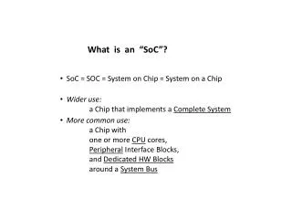
Networks for Multi-core Chip —A Controversial View. Shekhar Borkar Intel Corp. Outline. Multi-core system outlook On die network challenges A simpler but controversial proposal Benefits Summary. 45nm. 22nm. 16nm. 32nm. 10mm. 10mm. 10mm. 10mm. 8 Cores, 1V, 3GHz 3.5mm each core

E N D
Networks for Multi-core Chip—A Controversial View Shekhar Borkar Intel Corp.
Outline • Multi-core system outlook • On die network challenges • A simpler but controversial proposal • Benefits • Summary
45nm 22nm 16nm 32nm 10mm 10mm 10mm 10mm 8 Cores, 1V, 3GHz 3.5mm each core Total: 400MT 32 Cores, 1V, 3GHz 1.8mm each core Total: 1.6BT 64 Cores, 1V, 3GHz 1.3mm each core Total: 3.2BT 16 Cores, 1V, 3GHz 2.5mm each core Total: 800MT A Sample Multi-core System 10mm 65nm, 4 Cores 1V, 3GHz 10mm die, 5mm each core Core Logic: 6MT, Cache: 44MT Total transistors: 200M Core Cache 50% 50%
A Sample MC Network 5mm Packet Switched Mesh 16B=128 bit each direction 0.4mm @ 1.5u pitch 192GB/s Bisection BW 0.4mm
Mesh Power @ 3GHz, 1V • Power too high • Worse if link width scales up each generation • Most of the power dissipation is in router logic (not in the metal busses) • Cache coherency mechanism is complex
Why Mesh (or any other complex Network)? • Bus: Good at board level, does not extend well • Transmission line issues: loss and signal integrity, limited frequency • Width is limited by pins and board area • Broadcast, simple to implement • Point to point busses: fast signaling over longer distance • Board level, between boards, and racks • High frequency, narrow links • 1D Ring, 2D Mesh and Torus to reduce latency • Higher complexity and latency in each node Do you need point to point busses on a chip?
Bus for Multi-Core Chip? Issues: Slow, < 300MHz Shared, limited scalability? Solutions: Repeaters to increase freq Wide busses for bandwidth Multiple busses for scalability Benefits: Power? Simpler cache coherency Move away from frequency, embrace parallelism
Repeated Bus Arbitration: Each cycle for the next cycle Decision visible to all nodes Repeaters: Align repeater direction No driving contention O R R R R R R R R Assume: 10mm die, 1.5u bus pitch 50ps repeater delay
Other Bus Enhancements • Differential, low voltage swing • Twisted to reduce cross-talk • Optimal repeater placement • Not necessarily at the core • Higher bus frequency • Wide bus, 1024 bit or more, transfer lots of data in one cycle • Multiple busses for concurrency Employ interconnect engineering techniques
Bus Power and Bandwidth Includes bus and repeater power Full Swing 0.1V Differential Bus Mesh
Summary • Point to point busses are not necessary for multi-core chip • Rings and meshes were devised for point to point busses over long distances—overkill for on chip network? • Router power could be prohibitive • Wide bus or busses, may be adequate • Simple to implement • Simpler coherency • Lower power • Maybe lower latency • Go slower, wider, and simpler