Download
1 / 20
200 likes | 313 Views
The MICE Tracker. Introduction Tracker Design and Construction Readout Firmware QA Process & Results Cosmic Ray Data Taking First Results Next Steps. Introduction.

E N D
The MICE Tracker • Introduction • Tracker Design and Construction • Readout • Firmware • QA Process & Results • Cosmic Ray Data Taking • First Results • Next Steps M.Ellis - UKNF Meeting - 15th September 2008
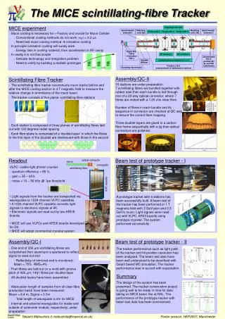
Introduction • The MICE tracker is responsible for position and momentum measurement of the beam going into and coming out of the cooling channel. • From this information and the time, extrapolated from the TOF chambers, the emittance of the beam can be determined. • The trackers are the closest detectors to the cooling channel, and so need to provide an accurate, efficient measurement of the muons in the presence of a potentially high background of X-rays from the RF cavities. • The technology chosen is scintillating fibres, readout by Visible Light Photon Counters. M.Ellis - UKNF Meeting - 15th September 2008
Tracker Design • Each of the two trackers consist of five stations (that measure the position of a particle). • These five stations are placed inside a uniform 4T solenoid. • Each station is made from 3 planes of scintillating fibre, oriented at 120º to each other, so as to give a redundant measurement of the position. • The planes are doublet layers of 350 mm diameter scintillating fibre from Kuraray. • There are over 1400 fibres per plane, read out in groups of seven (neighbouring fibres are ganged together into one clear fibre for read out). M.Ellis - UKNF Meeting - 15th September 2008
Tracker Design M.Ellis - UKNF Meeting - 15th September 2008
Tracker Construction M.Ellis - UKNF Meeting - 15th September 2008
Completed Tracker 1 M.Ellis - UKNF Meeting - 15th September 2008
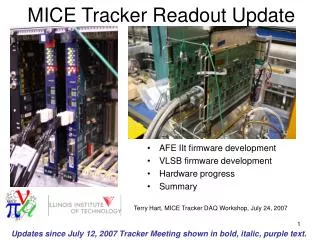
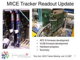
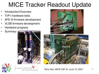
Readout • Very small fibres pose a problem for the light yield. • The solution we have chosen is to use Visible Light Photon Counters, which have high gain, low noise and very high QE (85-95%). • With this readout, the expected light yield is between 10 and 11 PE for muons in MICE. • VLPC cassettes from the D0 experiment are used, and the front end electronics boards are also D0’s AFE IIt boards, with modified firmware for MICE. • The complete data from a 1 ms spill is transferred via LVDS cables from the front end boards to VME memory modules, which will be read out once per spill. M.Ellis - UKNF Meeting - 15th September 2008
VLPC Performance M.Ellis - UKNF Meeting - 15th September 2008
Electronics M.Ellis - UKNF Meeting - 15th September 2008
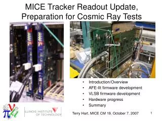
Firmware • New firmware for MICE required for both the AFEIIt and VLSB boards. • First versions of both suitable for running in MICE are being used for the cosmic ray test. • The AFEIIt firmware is currently limited to a maximum of about 150 muons in our 1 ms spill. • Work is ongoing in the US to increase the maximum rate through the implementation of zero suppression, multi-level buffering and some other enhancements to reduce the total time taken to digitise a trigger. • A first version of the zero suppression upgrade has been successfully tested at IIT and will hopefully be available for use in the cosmic ray rig soon. M.Ellis - UKNF Meeting - 15th September 2008
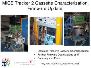
QA Process • Single VLPC cassette in the prototype MICE cryostat setup at Imperial College. • Radioactive source scanned over each station and boards readout with a special self-triggered mode that was developed for the QA. • Light yield measured for all 3 stations for each location of the source. • Due to rate and time constraints, we were unable to take data with the source over every channel, however the positions were chosen to sample a reasonable fraction of the active area of each station. M.Ellis - UKNF Meeting - 15th September 2008
QA Rig M.Ellis - UKNF Meeting - 15th September 2008
QA Results M.Ellis - UKNF Meeting - 15th September 2008
Cosmic Ray Data Taking • Complete tracker 1 is now setup in R8 at RAL. • Two scintillators made for a test beam at KEK in 2005 are used to provide a trigger (three new scintillators have been sent from Fermilab and should increase the trigger rate). • Tracker, waveguides, VLPC system and electronics are all the same equipment that will be used in MICE. • Readout is currently with the Fermilab designed Visual Basic code, will soon move to the DATE DAQ system that is used in MICE. • Analysis with the MICE software system (G4MICE). M.Ellis - UKNF Meeting - 15th September 2008
Track Residuals Expect: 0.431 mm M.Ellis - UKNF Meeting - 15th September 2008
Light Yield M.Ellis - UKNF Meeting - 15th September 2008
Next Steps • Sort out low light yield on waveguides 20 and 30. • Tracker 2 construction and cosmic ray testing. • Firmware development and testing. • Installation of tracks in the MICE hall once their solenoids arrive. M.Ellis - UKNF Meeting - 15th September 2008
Finally – 100 Events with 5 point Tracks: M.Ellis - UKNF Meeting - 15th September 2008