Download
1 / 37
370 likes | 619 Views
Freescale HCS12 微控制器 MC9S12DP256. 2005 年 8 月. 使用 HCS12 的第一步. 1) HCS12 技术概述 2) Operating Modes 工作模式 3) Resource Mapping 资源映射 4) External Bus Interface 外部总线接口 5) Port Integration Module 端口集成模块 6) Background Debug Mode 背景调试模块. Mode Register. $_0B. Special Single Chip

E N D
Freescale HCS12 微控制器MC9S12DP256 2005年8月
使用 HCS12的第一步 1) HCS12 技术概述 2) Operating Modes工作模式 3) Resource Mapping资源映射 4) External Bus Interface外部总线接口 5) Port Integration Module端口集成模块 6) Background Debug Mode背景调试模块
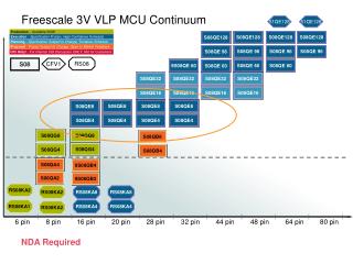
Mode Register $_0B Special Single Chip Emulation Exp Narrow Special Test Emulation Exp Wide Normal Single Chip Normal Exp Narrow Peripheral Normal Exp Wide 工作模式 CLOCK /RESET MODA MODB MODC MODA MODB MODC/BKGD RESET HCS12 Mode Pins are sampled and latched on rising edge of Reset . Sample Latch
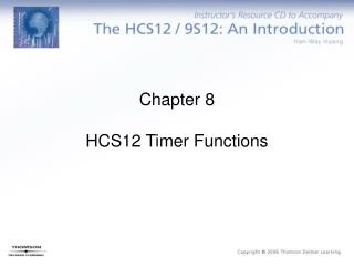
Modes of Operation MODC MODB MODA MODE ADDR DATA BDM 0 0 0 Special Single Chip 0 0 Active 0 0 1 Special Expanded Narrow 16 8 Allowed 0 1 0 Special Test 16 16 Allowed 0 1 1 Emulation Expanded Wide 16 16 Allowed 1 0 0 Normal Single Chip 0 0 Allowed 1 0 1 Expanded Narrow 16 8 Allowed 1 1 0 Peripheral Mode --- --- --- 1 1 1 Expanded Wide 16 16 Allowed MODA and MODB have active pulldowns during reset. MODC has the pull-up on the pin enabled after reset. Mode Pins are sampled and latched on rising edge of Reset
1 0 1 no write Expanded Narrow 1 1 0 no write Peripheral Mode 1 1 1 no write Expanded Wide MODC, MODB, MODA Write Capability MODC MODB MODA MODE MODx Write Capability MODC, B, A write anytime but not to 110 0 0 0 Special Single Chip 0 0 1 no write Special Expanded Narrow MODC, B, A write anytime but not to 110 0 1 0 Special Test 0 1 1 no write Emulation Expanded Wide MODB, A write once but not to 110 1 0 0 Normal Single Chip
内部存储器映射-寄存器 • 寄存器,RAM,EEPROM可以通过设置INITRG,INITRM,INITEE来重新分配他们的位置。 • 这些寄存器只能写一次,建议在初始化分配寄存器,RAM,EEPROM的位置。对每个INITxx赋值后,在其指令后需插入一空指令。 • 如果映射有冲突,寄存器具有最高优先级,与其重叠的RAM和EEPROM此时无效。 • 复位后,寄存器从0x0000开始,但可以被映射到64K空间内的前32K的范围内,而且映射的地址必须是2K的整数倍。 内部寄存器位置初始化寄存器 15 14 13 12 11 10 9 8 7 6 5 4 3 2 1 0 0 0 0 1 0 0 0 0 0 0 0 0 0 0 0 0 0x1000
内部存储器映射-RAM 1、复位后RAM区从0x1000开始,但可以被映射到64K字节空间内的任何16K字节块内。 比如从$0000-$3FFF,$4000-$7FFF. 2、RAM15-14用来决定RAM区映射到哪个16K的字节块中。RAM13-11不起作用 3、RAMHAL用来决定12KRAM是放在16K的后12K区域还是前12K区域 比如INITRM=9,则RAM从$9000到$BFFF共12K 内部RAM位置初始化寄存器
内部存储器映射-EEPROM • DP256有4K的EEPROM,通过INITEE的EEON位来使能 • 复位后,EEPROM区域从$0000开始,但可被映射任意64K空间中的4K字节块内。 • EE15-12决定16位EEPROM区域地址的前4位 比如:INITEE=0x11,则地址是从$1000开始 内部EEPROM位置初始化寄存器 EEON 1 = EEPROM IS ENABLED 0 = EEPROM IS DISABLED
映射优先级 优先级 资 源 BDM space (Internal) when BDM is active this 256 byte block of registers and ROM appear at $FF00 – $FFFF 最高 Register Space (Internal) – 1K bytes fully blocked for registers ... ... RAM (Internal) – 12K bytes ... EEPROM – 4K bytes ... On-Chip Flash EEPROM – 256K bytes 最低 Remaining external 如果资源映射时,发生重叠,则优先级高的资源有效 在扩展模式下,所有没有被内部资源用到的地址空间将被默认为外部存储器
强烈建议! • 尽量使用默认的资源映射设置! • 需要对资源映射时,注意不要使地址重叠,导致异常错误
存储器映射 & 工作模式 $0000 $0400 $1000 $4000 $FF00 $FFFF $0000 Registers $03FF Registers Registers Registers Mappable to any 2K Block within the first 32K. Mappable to any 4K Block 12K Mappable to any 16K Block and alignable to top or bottom 4K EEPROM 4K EEPROM 4K EEPROM $0000 EEPROM $0FFF $1000 $3FFF 12K RAM 12K RAM 12K RAM Page $3E $4000 Flash $7FFF 16K Flash (Fixed) 16K Flash (Fixed) 16K Flash (Fixed) $8000 Flash $BFFF 16Kx16 internal Flash Pages (Windowed) 16Kx16 Flash Pages (Windowed) 16Kx16 Flash Pages (Windowed) 16Kx48 external Flash Pages (Windowed) Page $3F $C000 Flash (Page 63) $FFFF 16K Flash (Fixed) 16K Flash (Fixed) 16K Flash (Fixed) BDM (If Active) VECTORS 单 片 VECTORS 扩展 $FF00 $FFFF 特殊单片模式
FLASH • $4000–$FFFF间的存储数据是可以访问的。 • 由于Flash 模块的地址范围超出了 HCS12 的64K (16-bit)地址空间,所以从 $8000–$BFFF被映射到若干16K字节大小的页框中。由PPAGE寄存器决定在当前访问的是哪一页。 • $8000 - $BFFF间共有64个可访问的页。使用PPAGE寄存器可以访问到地址在$8000–$BFFF间的所有共16页的16K字节。 • Flash模块中每个块包含许多行控制和状态寄存器,它们都位于的相同地址空间 INITRG + $100 - INITRG + $10F。通过Flash 配置寄存器选择有效的某行寄存器。 • MC9S12DP256 有7个引脚端口,端口K,用来仿真或者作为通用 I/O。其余六个端口用来决定哪一个Flash页正在被访问。其余的地址位放在 PPAGE 寄存器中。
FLASH • 除了硬件的分页机制外,另外增加了两条指令,用来调用页内函数。 • CALL指令类似于JSR,除了把分页窗返回地址放到堆栈中,它还会在CALL指令把新的8位的数据写到PPAGE之前,把PPAGE的当前值放到堆栈中。 • 调用CALL指令,需要用RTC指令返回 • 程序继续执行时,把PPAGE的值和分页窗口的地从堆栈中调出 • MC9S12DP256的PPAGE有6位,可以有1M的寻址范围 • 低地址范围的768K通过PPAGE $00到$2F来访问,它被保留用作外部存储器(当使用扩展模式时) • 高地址范围的256K由PPAGE的$30到$3F来访问,用作内部FLASH存储区
FLASH分页机制 • 所有的256K的FLASH可以通过16K的PPAGE窗口来访问,其中两个16K的页也可以通过固定地址($4000-7FFF, $C000-FFFF)来访问。 • $4000-$7FFF与$3E相对应,$C000-$FFFF与$3F相对应 • 这两个固定页克服了内存分页机制的一些缺点 • 采用分页机制,在某一页中的函数无法直接访问访问另一页中的数据 • 需要被其它页的函数访问的数据应该放在固定页中,或只有固定页的函数才能访问其他页的数据 • 因为复位和中断向量表只有16位,所以所有的中断服务程序和复位初始化程序必须从固定页中开始执行。 • 大部分中断服务程序可以放在非固定页中,部分的中断服务程序尤其起始部分要放在固定页中。通过CALL来调用非固定页中的函数,最后用RTI指令返回
FLASH-Codewarrior • Codewarrior引入两个关键字:near, far • Near函数用JSR或BSR来调用 • Far函数用CALL来调用 • 比如:void far func1(void);//func1函数放在非固定页中,可以被其他页的函数调用 • const int *far ptr;//指向常量的指针放在非固定页中,这个指针可以用来指向非固定页中的变量
Codewarrior内存模型 • Codewarrior支持3种不同的内存模型: • SMALL(默认),平面的64K的地址空间。所有的函数都是near • BANKED,即采用分页地址。所有的用户的函数都被默认为far • far类型的数据指针可以在SMALL和BANKED中使用 • LARGE, 默认为数据和代码均为分页模式。所有的函数和数据指针都是far类型。这种内存模型运行时间比较长,因此很少使用 MC9S12DP256最常用的是BANKED内存模型
Codewarrior分段 • 代码和数据可以被分组被Linker放在特定的存储区中 • #pragma用来给代码段或数据段命名并分配属性 • #pragma CODE_SEG定义一个代码段。 • NEAR规定本段中的函数用JSR来调用,即只能被本页函数调用,除非把它放在固定页中 • FAR规定本段中的函数用CALL来调用 • 如果没有规定NEAR或FAR,函数的类型由内存模型来决定 • 如果没有规定段,则代码放在DEFAULT_ROM中 • 所有跟在#pragma CODE_SEG后面的函数回放在该段中,直到下一个#pragma CODE_SEG出现,因此在头文件中,声明函数原型时,必须使用#pragma CODE_SEG #pragma CODE_SEG [NEAR|FAR] <segment_name> #include "functions.h" #pragma CODE_SEG FUNCTIONS void func1(void) { /* code */ }; void func2(void) { /* code */ }; #pragma CODE_SEG DEFAULT #pragma CODE_SEG FUNCTIONS void func1(void); void func2(void); #pragma CODE_SEG DEFAULT
Codewarrior-数据段 • #pragma DATA_SEG把全局变量发到一个特定的段中 • SHORT规定本段中的全局变量采用直接寻址方式。但是这段变量必须放在$0000到$00FF中 • 如果没有#pragma DATA_SEG,全局变量将会被放到DEFAULT_RAM段中 • 所有跟在#pragma DATA_SEG后面的函数回放在该段中,直到下一个#pragma DATA_SEG出现 • 如果全局变量被其他文件使用,则在其他文件中声明变量时,必须重复使用相同的#pragma DATA_SEG #pragma DATA_SEG [SHORT] <segment_name>
Codewarrior-常数段 • #pragma CONST_SEG定义了一个常数段 • PPAGE规定常数的访问要通过PPAGE, 常数可以放在非固定页 • 如果没有PPAGE,变量应该放在固定页 • 如果没有#pragma CONST_SEG,常数会被放在ROM_VAR • 所有跟在#pragma CONST_SEG后面的函数回放在该段中,直到下一个#pragma CONST_SEG出现 • 如果全局变量被其他文件使用,则在其他文件中声明变量时,必须重复使用相同的#pragma CONST_SEG #pragma CONST_SEG [PPAGE] <segment_name> #pragma CONST_SEG B extern const int var2; #pragma CONST_SEG DEFAULT
Codewarrior-中断函数 • 中断函数需要放在固定页 • #pragma TRAP_PROC表示以下的函数将用RTI指令返回 • 如果使用interrupt关键字,则不必再写#pragma TRAP_PROC • __NEAR_SEG显性地表示这段代码放在固定页 #pragma CODE_SEG __NEAR_SEG NON_BANKED #pragma TRAP_PROC void interrupt_func1(void) { /* code */ }; #pragma CODE_SEG DEFAULT #pragma CODE_SEG __NEAR_SEG NON_BANKED void interruptinterrupt_func1(void) { /* code */ }; #pragma CODE_SEG DEFAULT
Memory Map $0000 $0400 $1000 $4000 $8000 $C000 $FF00 $FFFF $0000 $0400 $1000 $4000 $8000 $C000 $FF00 $FFFF $0000 $0400 $1000 $4000 $8000 $C000 $FF00 $FFFF Registers- Mappable to any 2k Block within the first 32kByte. EEPROM- Mappable to any 4k Block RAM- 12k Mappable to any 16k Block and alignable to top or bottom. Registers Registers Registers EEPROM EEPROM EEPROM RAM RAM RAM 16kByte fixed Flash 16kByte fixed Flash External Memory 16kByte paged Flash 16kByte paged Flash 16kByte fixed Flash 16kByte fixed Flash Vectors Vectors BDM Expanded Mode Normal Single Chip Mode Special Single Chip Mode
External Bus Interface A/D[15:0] R/W ECLK LSTRB HCS12 • AD[15:0] - Address/Data Bus • ECLK - E clock 1/2 Xtal Frequency -> used for demultiplexing and external bus timing • LSTRB - Low byte strobe signal -> used to enable data on the low byte of the address bus • R/W - Read=1, Write= 0 -> used to determine the data bus direction
Read/Write Bus Cycle Latch Address
Memory Interface Example TO OTHER DEVICES [D15:8] ECLK CE OE R/W CE OE [D7:0] 8Kx8 RAM 8Kx8 RAM Address Latch & Decode Logic LSTRB HCS12 AD [15:0 ] WE WE ADDR [A12:1] DATA [15:0] ADDRESS B15 B8 B7 B0 0000 - - - - FFFE 0001 - - - - FFFF . . . . . . . . . . . . MUXED_BUS WIDE_MODE D15 - D8 D7 - D0
Byte Select Logic ADDR_BUS CS LOGIC CE CE OE OE A0 LSTRB R/W ECLK EVEN ODD WE WE MEM INT. D7-0 D15-8 DATA BUS
资源映射 Address Offset $0013 MISC - Miscellaneous Mapping Control Register综合映射控制寄存器 EXSTR BIT DEFINITION FOR EXTERNAL ADDRESS SPACE ROMON 1 = Enable Flash in memory map 0 =Disable Flash in memory map EXSTR1 EXSTR0 NUMBER OF CLKS 0 0 0 0 1 1 1 0 2 1 1 3 ROMHM 1 = Disable 16K Flash Direct Access @$4000 - $7FFF 0 = 16K Flash page $3E accessible @$4000 - $7FFF (Note: This page can still be accessed through the Program Page Window) EBICTL - External Bus Interface Control Address Offset $000E ESTR - E CLK Stretch Enable 1 = E Clock Stretches High High on External Accesses 0 = E Clock Stretches Disabled
GP I/O PORTS Mux Ports Multiplexed Address/Data Bus DDRA DDRB PORT A PORT B DDRx 1 = PIN IS OUTPUT 0 = PINIS INPUT DDRA - Port A Data Direction Register DDRB - Port B Data Direction Register 7.......………………....................................................0 Address Offset $0003 7............………..............................................0 Address Offset $0002 Read/write Read/write RST: 0……..……………………………………………………..0 RST: 0..................………..........................................0 PORTA - Port A Data Register PORTB - Port B Data Register 7..........……………..................................................0 7..…………………........................................................0 $0000 $0001 Read/write Read/write RST: U…….…………………………………………………..….U RST: U…….…………………………………………………..….U Expanded ADDR15/ ADDR14/ ADDR13/ ADDR12 /ADDR11/ ADDR10/ ADDR9/ ADDR8/ & Periph:DATA15 DATA14 DATA13 DATA12 DATA11 DATA10 DATA9 DATA8 Expanded ADDR15/ ADDR14/ ADDR13/ ADDR12/ ADDR11/ ADDR10/ ADDR9/ ADDR8/ Narrow DATA15/ DATA14/ DATA13/ DATA12/ DATA11/ DATA10/ DATA9/ DATA8/ DATA7 DATA6 DATA5 DATA4 DATA3 DATA2 DATA1 DATA0 Expanded ADDR7/ ADDR6/ ADDR5/ ADDR4 /ADDR3/ ADDR2/ ADDR1/ ADDR0/ & Periph:DATA7 DATA6 DATA5 DATA4 DATA3 DATA2 DAT1 DATA0 Expanded ADDR7/ ADDR6/ ADDR5/ ADDR4 /ADDR3/ ADDR2/ ADDR1/ ADDR0/ Narrow
PORTE Registers PORTE - PORTE Register Address Offset $0008 Reset: Unaffected Alt. Pin Function XCLKS/ MODB/ MODA LSTRB R/W IRQ XIRQ NOACC IPIPE1/ IPIE0 ECLK TAGLO SCGTO RCRTO XCLKS - External Clock This pin is sampled on the rising edge of Reset to select the device clock source. NOACC - No Access This output signal indicates the current access is unused or free cycle. TAGLO - Instruction Low Byte Tagging This output signal may be used to tag the low byte of the instruction. DDRE - PORTE Data Direction Register Address Offset $0009 Reset: 0 0 0 0 0 0 0 0 DDREx =0 pin is input =1 pin is output
PORTE Assignments PEAR - PORTE Assignment Register Address Offset $000A Reset: 0 0 0 0 0 0 0 0 Special single chip Reset: 0 0 1 0 1 1 0 0 Special Test Reset: 0 0 0 0 0 0 0 0 Peripheral Reset: 1 0 1 0 1 1 0 0 Emulation Exp Nar Reset: 1 0 1 0 1 1 0 0 Emulation Exp Wide Reset: 0 0 0 1 0 0 0 0 Normal Single Chip Reset: 0 0 0 0 0 0 0 0 Normal Exp Nar Reset: 0 0 0 0 0 0 0 0 Normal Exp Wide PORTE Assignment Register may be used to choose between bus control or GPI/O functions. NOACCE - CPU no Access Output Enable (Write once) 1 = Port E Pin 7 is output which indicates CPU free cycle 0 = Port E Pin 7 is GPI/O PIPOE - Pipe Status Signal Output Enable (Write once) 1 = Port E Pins[6:5] are used as IPIPE1 and IPIPE0 for instruction queue tracking 0 = Port E Pins[6:5] are used as GPI/O NECLK - No External E Clock (Write anytime) 1 = Port E Pin 4 used as GPI/O 0 = Port E Pin 4 is E Clock output pin LSTRE - Low Strobe(LSTRB) Enable (Write once) 1 = Port E Pin 3 is used as LSTRB bus control signal 0 = Port E Pin 3 is used as GPI/O RDWE - Read/Write Enable (Write once) 1 = Port E Pin 2 is configured as R/W bus control signal 0 = Port E Pin 2 Is configured as GPI/O
HCS12 Device Identification The part ID is located in two 8-bit registers PARTIDH and PARTIDL. The read-only value is a unique part ID for each revision of the die. The coding is as follows: Bit 15-12: Major family identifier Bit 11-8: Minor family identifier Bit 7-4: Major mask set revision number including FAB transfers Bit 3-0: Minor - non full - mask set revision
HCS12 Memory Identification The device memory sizes are located in two 8-bit registers MEMSIZ0 and MEMSIZ1. Also reference - EB386 “Family Compatibility Considerations” for information on how to configure a larger derivative to act as a smaller part.
配置举例 如何设置系统 - 选择工作模式 (硬件 / 软件) - 资源映射 (内部 / 外部) - 设置时钟 - 设置PIM - 初始化外设…
配置举例 • 创建一个带全局变量的工程文件 • 编译后,打开调试界面 • 在component菜单中打开一个新的Memory窗口 • Memory:1窗口中修改0x0010:INITRM 09 49 40 89 80 • Memory:2窗口中显示不同地址中的内容 1000 5000 4000 9000 8000 • 当INITRM的值改变时,变量在RAM中的位置也会改变
Memory:2窗口中 显示不同地址中的内容 1000 5000 4000 9000 8000 Memory:1窗口中 修改0x0010:INITRM 09 49 40 89 80