Download
1 / 26
260 likes | 267 Views
Overview of the INL Fusion Safety Program. PbLi-T Workshop 11-12 June 2007 Idaho Falls, ID. Outline. STAR Dust Tritium Material Interactions and Permeation Fusion Safety Codes Risk Waste Management Safety Design Analysis Summary. STAR Floorplan Layout. Glovebox TCS. Stack monitor.

E N D
Overview of the INL Fusion Safety Program PbLi-T Workshop 11-12 June 2007 Idaho Falls, ID
Outline • STAR • Dust • Tritium Material Interactions and Permeation • Fusion Safety Codes • Risk • Waste Management • Safety Design Analysis • Summary
STAR Floorplan Layout Glovebox TCS Stack monitor Tritium SAS Chemical reactivity D-ion implantation TPE 2LiF-BeF2 preparation, purification and testing MS tritium exp MS corrosion exp 15,000 Ci tritium limit Segregation of operations Gloveboxes and hoods Tritium cleanup system Once-through room ventilation
Secondary inlet U-bed-1 Primary outlet U-bed-2 Star Tritium Storage and Assay System SAS manifold and vacuum pumps SAS manifold with U-beds SAS glovebox Setup
STAR Tritium Cleanup System (TCS) Inlet Outlet IC Inlet sample loop Condenser Control Heat exchanger MS water Mole sieve bed Blower Catalyst beds
Tritium at STAR • Useable tritium inventory now 1300 Ci • 300 Ci in equimolar H2:D2:T2 calibration standard • 1000 Ci T2 available for experiments • shipments from SRS limited to 1000 Ci with standard TYPE-A shipping container • next shipment (1000 Ci) expected in Fall 2007 Shipping Vessel (1 available)
History of TPE Summer/ Fall 2002 - Uncrate and decon ancilliary components January 2003 - Modify plans for location of experiment, decide on PermaCon structure, initiate facility design changes. June 2003- PermaCon installed, TPE glovebox uncrated. 2004- Reassembly and system interface design activities March 2002 - Extraction, loading, and transport May 1995 - First tritium plasma experiments at TSTA September 2000 - Final tritium plasma experiments at TSTA Spring & Summer 2005 Electrical Service re-design & construction, experiment & facility interface assemblies completed Fall 2005 - Integrated systems testing initiated April 8, 2002 - Depart LANL February 2001 - Begin D&D efforts of TPE December 2001 - Final pump out of system; close all valves January 2002 - Preparation for shipment December 2005 - First plasma testing (non-tritium) April 10, 2002 - Arrival at INL STAR Facility
Planned Research Agenda for TPE • Study uptake, retention and permeation in PFCs • Measurement of bulk tritium transport properties (diffusivity, solubility, dissociation/recombinatino rates) • Monomaterials (Be, W, C) • Mixed materials • Bonded and/or duplex structures • Effects of neutron dose and irradiation temperature on tritium trapping • Certification of these structures for ITER • Use of tritium in the plasma will enable low level measurements needed for such research
Flibe Tritium Experiment • Tritium provided in pressurized vessel containing D2/T2 mixture • Glovebox setup to contain potential leaks • Localized tritium cleanup will be connected • GC column accurately measures H concentration; tritium release measured with ion chamber • well-characterized with D2; now experiment with T2
Permeation Coating Barrier Experments Thermal Cycle Performance of He Pipe Permeation Barriers • simulates thermal stress degradation of permeation barrier coatings for He pipes • configuration matched to TBM design for coated components • utilize tritium for barrier technology qualification • external thermal cycles followed by testing in permeation rig for integrated effects • in-situ thermal cycling in permeation rig for barrier dynamic response
Dust generation ITER Key Issues: chemical reactivity, radioactivity content, dust explosions. Science: understand and model underlying formation mechanisms to estimate inventories expected in fusion ITER Dust Strategy from EDA Demonstration of the filtered vacuum collection technique Key scientific issues needing resolution
Specific Surface Area Dust Characterization Particle Size Distribution, Specific Surface Area, Surface Mass Density, Composition, Shape and Tritium Content Comparison of Size Distributions Dust Size versus Surface Mass Density R&D continues to resolve the issues
Research Agenda for Dust • Continued characterization in existing tokamaks • Mobilization testing • Chemical reactivity of dust in grooves • Dust explosion testing • Monitoring and removal evaluation • Improved strategy for ITER
Major Accomplishments in Risk Assessment for Fusion • Work on component failure rate data to support quantitative safety assessment continues to be very successful. • Initially, component failure rates were collected from handbooks and applied to fusion. • Now, through IEA Task 5, we collect fusion facility operating experience data from TLK, TPL, and the former TSTA; and tokamak data from DIII-D and JET. • Independent data sets validate the failure rate values. • Occupational safety is a new area for risk assessment. • ITER IT has plans to perform a room-by-room overall assessment of the ITER facility to identify occupational hazards • Occupational injury rates have been collected from several US tokamaks and large particle accelerators • WE-FMEA method was developed to address highly hazardous equipment failures in a fusion facility, such as high energy pipe breaks that have caused worker fatalities in the power industry
The Hazard Zone of the Worker Exposure - Failure Modes and Effects (WE-FMEA)
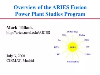
INL FSP Support of the ITER Project • The FSP is supporting the ITER Project through three Implementing Task Agreements (ITA): • Fusion Safety Code Support • Provide International Team (IT) with the latest fusion versions of the MELCOR and ATHENA codes, documentation, validation, and support and assistance at operation of the codes. • Delivered MELCOR 1.8.5, upgraded ice layer model for cryogenic surfaces, and developed a beryllium dust layer oxidation model for MELCOR • Assist the ITER IT in producing the QA documentation for MELCOR and safety analyses for ITER’s Report on Preliminary Safety (RPrS) • Magnet Safety • Update the MAGARC code to current ITER design for TF and PF coils, include new R&D results on insulation failure behavior at elevated temperatures, apply the MAGARC code to various ITER magnet safety studies • Upgraded insulation and magnet parameters, implemented arc limit model, applied MAGARC to ITER-FEAT TF and PF magnet unmitigated quench events • Develop magnet Busbar arc capability for MAGARC • Dust Issues • Characterize and quantify amounts generated during ITER operation • Reactivity/explosivity, mobilization, and transport during accident conditions
0 10 INL92 88% dense MELCOR dust layer model (Dust=0.7g/cm3, dp= 20mm) - 3 10 INL98 88% dense INL Dust - 6 Beryllium oxidation rate (kg/m2-s) 10 - 9 10 INL fully dense - 12 10 20 5 10 15 10,000/T (K) MELCOR Code Heat Structure Dust Layer Oxidation Model • A beryllium dust layer oxidation model was developed for ITER to simulate oxidation of a dust layer of dust that has settled onto a heated surface inside of a fusion device • This model is based on measured oxidation reaction rates for fully dense beryllium, binary gaseous diffusion of oxygen or steam into the dust layer, and BET measured specific surface area for beryllium dust • Application is for slow vacuum vessel pressurization events from in-vessel loss-of-cooling accidents (LOCAs) and loss-of-vacuum accidents (LOVAs)
Winding pair Radial direction Axial direction Radial direction Axial direction 1500 Inline arcs 1000 Voltage (V) voltage drops 500 0 0.00 0.25 0.72 0.50 0.54 0.75 0.36 Height (m) 0.18 1.00 Width (m) 0.00 Time 110s MAGARC Poloidal Field Coil Development • The MAGARC code was recently modified to analyze unmitigated quench events in ITER poloidal field (PF) magnets • This modification include the electrical characteristics of the two-in-hand winding pair of the ITER PF coils and limits on the number of arcs that can form in the magnet during unmitigated quench events based on an energy minimization principle.
3000 8 Inline 2000 Radial 6 Axial Lead voltage drop (V) 1500 Number of arcs 4 1000 2 500 0 0 0 150 300 450 600 Time (s) 4.0 3.0 Coil current (kA) 2.0 0.8 1.0 0.0 0.6 0 150 300 450 600 Time (s) Quench fraction 0.12 0.4 0.08 0.2 Melt volume (m3) 0.04 0.0 0 150 300 450 600 0 150 300 450 600 0.00 Time (s) 0 150 300 450 600 Time (s) Time (s) MAGARC Poloidal Field Coil Application • MAGARC code application to unmitigated quench events in ITER poloidal field (PF) magnets
Future Safety Code Activities • MAGARC capabilities will be expanded to treat arcs in magnet busbars by including the magnetic effects of the arc that forms between the leads of a busbar. As part of an international collaboration, this new capability will be validated against data that has recently been obtained from the MOVARC experiment at FzK in Germany • Work with the ITER IT to provide the necessary quality assurance documentation required for ITER licensing for the MELCOR code • Continue in support of the licensing process for the US DCLL TBM to complete Dossier on Safety for this TBM concept
0.25 Vacuum Vessel Cryostat 0.20 0.15 Pressure (MPa) 0.10 0.05 0.00 3600 3700 3800 3900 4000 Time (s) MELCOR CodeApplied to ARIES-CS • ARIES-CS has Dual Cooled Liquid Lead Lithium (DCLL) Blanket • This blanket concept employees reduced activation ferritic steel (RAFS) for the structure, cooled by 8 MPa helium, and a self-cooled breeding zone cooled by flowing PbLi. • Helium pressurization accidents will be a concern for this concept, with the reactor cryostat serving as secondary radioactivity and pressure confinement • Because stellarator plasmas do not disrupt, the beyond design basis bypass accident (BDBA) of concern may be a heat exchanger tube breach in the PbLi/Brayton cycle system, leaking 10 MPa helium into the blanket causing a blanket break and pressurization of the vacuum vessel Initial results for in-vessel FW helium LOCA
MELCOR Code Applied to US Test Blanket Module Safety Assessment • Evaluate consequences to ITER from accidents in the proposed US DCLL Test Blanket module (TBM) • To date three accident scenarios have been investigated: • In-vessel TBM coolant leaks • In-TBM breeding zone coolant leaks • Ex-vessel TBM cooling system leaks • No significant impacts on ITER safety have been identified, but assessment is still ongoing Internal PbLi flow • All FS structures are He-cooled by 8 MPa • PbLi self-cooled flows in poloidal direction He out He in PbLi concentric inlet/outlet pipe
Recent Trends in Radwaste Management • Options: • Disposal in repositories: LLW (WDR < 1) or HLW (WDR > 1) • Recycling – reuse within nuclear facilities (dose < 3000 Sv/h) • Clearance – release slightly-radioactive materials to commercial market if CL < 1. • Tighter environmental controls and the political difficulty of building new repositories worldwide may force fusion designers to promote recycling and clearance, avoiding geological disposal No radwaste burden on future generation. • There’s growing international effort in support of this new trend. • Recycling may not be economically feasible for all fusion components. • Recycling of liquids and solids may generate limited amount of radioactive waste that needs special treatment.
S&E considerations are critical for the success of IFE • IFE has both radiological and toxicological hazards: • Tritium fuel, activated structural material, activated dust, activated coolants or coolant impurities, and activated gases • Chemically toxic materials (i.e.: Hg, Pb) • Energy sources that can mobilize these hazardous materials include: • chemical energy, decay heat, pressure energy, electrical energy and radiation • In the US, current IFE S&E activities, are focused on a few programs: • The High Average Laser Program (HAPL) • TheZ-IFEProgram • The National Ignition Facility (NIF): not exactly an IFE program but closely linked to the future of IFE research
Summary • US S&E research continues to help improve fusion facility design in terms of accident safety, worker safety, and waste disposal. • The R&D underway and currently planned in the areas of dust and tritium source terms will answer important questions for ITER and future machines. • Regulatory approval of ITER and the associated verification and validation activities for our fusion safety codes and risk and reliability methods will provide greater confidence in application of these tools to evaluate public and worker safety of future fusion facility designs. • The resurgence of nuclear fission reactor construction activities worldwide will cause increased attention to waste management issues associated with nuclear power which in turn should help fusion as it develops a long term waste management strategy consistent with on-going US regulation. • Safe and environmentally sound operation of both ITER and NIF will be important public demonstrations of the S&E potential of fusion.