Download
1 / 26
260 likes | 299 Views
Kinematics of Mobile Robots. Forward Kinematics of Differential drive. Where can we find differential drives?. Braitenberg Vehicles Micromouse Most of our robots Unicycle Segway Many many others. Kinematics of Differential drive. Differential Drive is the most common kinematic choice.

E N D
Where can we find differential drives? Braitenberg Vehicles Micromouse Most of our robots Unicycle Segway Many many others
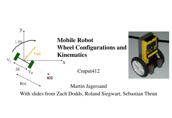
Kinematics of Differential drive Differential Drive is the most common kinematic choice - difference in wheels’ speeds determines its turning angle All of the miniature robots… Pioneer, Rug warrior Questions (forward kinematics) Given the wheel’s velocities or positions, what is the robot’s velocity/position ? VL Are there any inherent system constraints? VR 1) Specify system measurements 2) Determine the point (the radius) around which the robot is turning. 3) Determine the speed at which the robot is turning to obtain the robot velocity. 4) Integrate to find position.
Kinematics of Differential drive 1) Specify system measurements y - consider possible coordinate systems VL x q 2d VR (assume a wheel radius of 1)
Kinematics of Differential drive – radius of turning 1) Specify system measurements y - consider possible coordinate systems 2) Determine the point (the radius) around which the robot is turning. VL x q 2d VR ICC “instantaneous center of curvature” (assume a wheel radius of 1)
Kinematics of Differential drive – angular velocity 1) Specify system measurements y - consider possible coordinate systems 2) Determine the point (the radius) around which the robot is turning. - to minimize wheel slippage, this point (the ICC) must lie at the intersection of the wheels’ axles VL x - each wheel must be traveling at the sameangular velocity q 2d VR ICC “instantaneous center of curvature” = angular velocity (assume a wheel radius of 1)
Kinematics of Differential drive 1) Specify system measurements y - consider possible coordinate systems 2) Determine the point (the radius) around which the robot is turning. w - to minimize wheel slippage, this point (the ICC) must lie at the intersection of the wheels’ axles VL x - each wheel must be traveling at the same angular velocity around the ICC q 2d VR ICC “instantaneous center of curvature” (assume a wheel radius of 1)
Kinematics of Differential drive y x 1) Specify system measurements - consider possible coordinate systems 2) Determine the point (the radius) around which the robot is turning. w - each wheel must be traveling at the same angular velocity around the ICC VL 3) Determine the robot’s speed around the ICC and its linear velocity 2d VR ICC w(R+d) = VL R w(R-d) = VR robot’s turning radius (assume a wheel radius of 1)
Kinematics of Differential drive y x 1) Specify system measurements - consider possible coordinate systems 2) Determine the point (the radius) around which the robot is turning. w - each wheel must be traveling at the same angular velocity around the ICC VL 3) Determine the robot’s speed around the ICC and then linear velocity 2d VR ICC “instantaneous center of curvature” ICC w(R+d) = VL R w(R-d) = VR robot’s turning radius Thus, w = ( VR - VL ) / 2d R = 2d ( VR + VL ) / ( VR - VL ) (assume a wheel radius of 1)
Kinematics of Differential drive – robot’s velocity y x 1) Specify system measurements - consider possible coordinate systems 2) Determine the point (the radius) around which the robot is turning. w - each wheel must be traveling at the same angular velocity around the ICC VL 3) Determine the robot’s speed around the ICC and then linear velocity 2d VR ICC w(R+d) = VL R w(R-d) = VR robot’s turning radius Thus, w = ( VR - VL ) / 2d R = 2d ( VR + VL ) / ( VR - VL ) So, the robot’s velocity is V = wR = ( VR + VL ) / 2
Kinematics of Differential drive – integrate to obtain position y x 4) Integrate to obtain position Vx = V(t) cos(q(t)) w(t) V(t) Vy = V(t) sin(q(t)) q(t) VL Vx 2d VR ICC “instantaneous center of curvature” ICC R(t) robot’s turning radius with w = ( VR - VL ) / 2d R = 2d ( VR + VL ) / ( VR - VL ) V = wR = ( VR + VL ) / 2 What has to happen to change the ICC ?
Kinematics of Differential drive y x 4) Integrate to obtain position Vx = V(t) cos(q(t)) w(t) Vy = V(t) sin(q(t)) Thus, x(t) = ∫ V(t) cos(q(t)) dt VL y(t) = ∫ V(t) sin(q(t)) dt 2d q(t) = ∫w(t) dt VR ICC R(t) robot’s turning radius with w = ( VR - VL ) / 2d R = 2d ( VR + VL ) / ( VR - VL ) V = wR = ( VR + VL ) / 2
Kinematics of Differential drive – velocity components Velocity Components y speed Vx = V(t) cos(q(t)) Vy = V(t) sin(q(t)) w(t) Thus, x(t) = V(t) cos(q(t)) dt VL x y(t) = V(t) sin(q(t)) dt 2d q(t) = w(t) dt VR ICC Kinematics R(t) robot’s turning radius with w = ( VR - VL ) / 2d R = 2d ( VR + VL ) / ( VR - VL ) V = wR = ( VR + VL ) / 2 What has to happen to change the ICC ?
Inverse Kinematics – the problem Given a desired position or velocity, what can we do to achieve it? Key question: y x VL (t) VR(t) starting position final position
Inverse Kinematics – one solution Given a desired position or velocity, what can we do to achieve it? Key question: y x VL (t) VR(t) starting position final position
Inverse Kinematics – another solution Given a desired position or velocity, what can we do to achieve it? Key question: y x VL (t) VR(t) starting position final position
Inverse Kinematics – many numerical solutions to equations Given a desired position or velocity, what can we do to achieve it? Key question: y Need to solve these equations: x = V(t) cos(q(t)) dt y = V(t) sin(q(t)) dt x VL (t) q = w(t) dt w = ( VR - VL ) / 2d VR(t) V = wR = ( VR + VL ) / 2 starting position final position for VL (t) and VR(t) . There are lots of solutions...
Inverse Kinematics – finding the best solution Given a desired position or velocity, what can we do to achieve it? Key question: y Finding some solution is not hard, but finding the “best” solution is very difficult... x VL (t) • quickest time • most energy efficient • smoothest velocity profiles VR(t) starting position final position VL (t) t VL (t) It all depends on who gets to define “best”...
Inverse Kinematics - decomposition Usual approach: decompose the problem and control only a few DOF at a time Differential Drive y x VL (t) VR(t) starting position final position
Inverse Kinematics – decomposition for Differential Drive Usual approach: decompose the problem and control only a few DOF at a time Differential Drive (1) turn so that the wheels are parallel to the line between the original and final position of the robot origin. y -VL (t) = VR (t) = Vmax x VL (t) VR(t) starting position final position
Inverse Kinematics Usual approach: decompose the problem and control only a few DOF at a time Differential Drive (1) turn so that the wheels are parallel to the line between the original and final position of the robot origin. y -VL (t) = VR (t) = Vmax (2) drive straight until the robot’s origin coincides with the destination x VL (t) VL (t) = VR (t) = Vmax VR(t) starting position final position
Inverse Kinematics Usual approach: decompose the problem and control only a few DOF at a time Differential Drive (1) turn so that the wheels are parallel to the line between the original and final position of the robot origin. y -VL (t) = VR (t) = Vmax (2) drive straight until the robot’s origin coincides with the destination x VL (t) VL (t) = VR (t) = Vmax VR(t) (3) rotate again in order to achieve the desired final orientation starting position final position -VL (t) = VR (t) = Vmax VL (t) t VR (t)
Problem Represent the forward and inverse kinematics for this robot using notation from the previous lecture.
Sources • Prof. Maja Mataric • Dr. Fred Martin • Bryce Tucker and former PSU students • A. Ferworn, • Prof. Gaurav Sukhatme, USC Robotics Research Laboratory • Paul Hannah • Reuven Granot, Technion • Dodds, Harvey Mudd College