Download
1 / 33
400 likes | 813 Views
The Instruction Set Architecture Level. Chapter 5. Expanding Opcodes. Consider an ( n+k ) bit instruction with a k-bit opcode and a single n-bit address. This instruction allows 2 k different operations and 2 n addressable memory cells.

E N D
The Instruction SetArchitecture Level Chapter 5
Expanding Opcodes • Consider an (n+k) bit instruction with a k-bit opcode and a single n-bit address. • This instruction allows 2k different operations and 2n addressable memory cells. • Alternatively, the same n+k bits could be broken up into a (k-1) bit opcode, and an (n+1) bit address. • This means only half as many instructions but either twice as much memory addressable, or the same amount of memory but with twice the resolution. • A (k+1) bit opcode and an (n-1) bit address gives more operations, but less addressable cells, or poorer resolution and the same amount of memory addressable. • Consider a machine with 16-bit instructions with 4-bit addresses.
Expanding Opcodes • Use opcodes 0 to 14 as three-address instructions but interpret opcode 15 differently. • Opcode 15 means that opcode is contained in bits 8 to 15 instead of 12 to 15. • Instructions with 1111 in the leftmost 4 bits, and either 1110 or 1111 in bits 8 to 11 are treated specially. • They are treated as though their opcodes are in bits 4 to 15 and results in 32 new opcodes. • For bits 1111 1111 1111 in bits 4 to 15 there will be 16 instructions with no address by having bits 0000 to 1111 in bits 0 to 3. • All the 16 bits represent the opcode with no address field.
Expanding Opcodes • Using variable size opcodes, the instructions can all be kept the same length, by assigning the shortest opcodes to the instructions that need the most bits to specify other things. • Also, the size of the average instruction can be minimized by choosing opcodes that are shortest for common instructions, and longest for rare instructions. • On an extreme case, it is possible to minimize the average instruction length by encoding every instruction to minimize the number of bits needed. • Unfortunately, this would result in instructions of various sizes not even aligned on byte boundaries. • It is important to have instructions aligned on byte boundaries for rapid decoding of instructions.
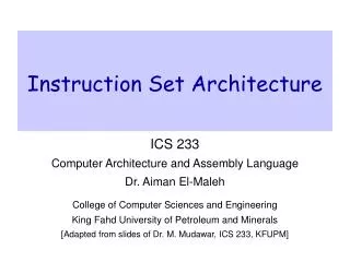
The Core i7 Instruction Formats Figure 5-13. The Core i7 instruction formats. • The Core i7 instruction formats are highly complex and irregular, having up to six variable-length fields, of which five are optional. • For two-operand instructions, if one operand is in memory, the other may not be in memory. • Thus instructions exist to add two registers, add a register to memory, and add memory to a register, but not to add a memory word to another memory word.
The Core i7 Instruction Formats • On earlier Intel architectures, all opcodes were 1 byte, though the concept of a prefix byte was used extensively for modifying some instructions. • A prefix byte is an extra opcode stuck onto the front of an instruction to change its action. • The WIDE instruction in IJVM is an example of a prefix byte. • Unfortunately, at some point during the evolution, Intel ran out of opcodes, so one opcode, 0xFF, was designated as an escape code to permit a second instruction byte. • The individual bits in the Core i7 opcodes do not give much information about the instruction. • The only structure in the opcode field is the use of the low-order bit in some instructions to indicate byte/word, and the use of the adjoining bit to indicate whether the memory address (if it is present) is the source or the destination.
The Core i7 Instruction Formats • Thus in general, the opcode must be fully decoded to determine what class of operation is to be performed—and thus how long the instruction is. • This makes high-performance implementations difficult, since extensive decoding is necessary before it can even be determined where the next instruction starts. • Following the opcode byte in most instructions that reference an operand in memory is a second byte that tells all about the operand. • These 8 bits are split up into a 2-bit MOD field and two 3-bit register fields, REG and R/M. • Sometimes the first 3 bits of this byte are used as an extension for the opcode, giving a total 11 bits for the opcode. • However, the 2-bit mode field means that there are only four ways to address operands and one of the operands must always be a register.
The Core i7 Instruction Formats • Logically, any of EAX, EBX, ECX, EDX, ESI, EDI, EBP, ESP should be specifiable as either register, but the encoding rules prohibit some combinations and use them for special cases. • Some modes require an additional byte, called SIB (Scale, Index, Base), giving a further specification. • This scheme is not ideal, but a compromise given the competing demands of backward compatibility and the desire to add new features not originally envisioned. • In addition to all this, some instructions have 1, 2, or 4 more bytes specifying a memory address (displacement) and possibly another 1, 2, or 4 bytes containing a constant (immediate operand).
OMAP4430 ARM CPU Instruction Formats • The OMAP4430 ARM ISA consists of both 16- and 32-bit instructions, aligned in memory. • Instructions are generally simple, specifying only a single action. • A typical arithmetic instruction specifies two registers to supply the source operands and a single destination register. • The 16-bit instructions are pared-down versions of the 32-bit instruction. • They perform the same operations, but allow only two register operands (i.e., the destination register must be the same as one of the inputs) and only the first eight registers can be specified as inputs. • The ARM architects called this smaller version of the ARM ISA the Thumb ISA
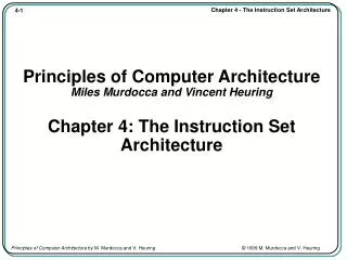
OMAP4430 ARM CPU Instruction Formats Figure 5-14. The 32-bit ARM instruction formats.
OMAP4430 ARM CPU Instruction Formats • Additional variants allows instructions to supply a 3, 8, 12, 16, or 24-bit unsigned constant instead of one of the registers. • For a load instruction, two registers (or one register and an 8-bit signed constant) are added together to specify the memory address to read. • The data are written into the other register specified. • Some of the formats have the same fields (e.g., LONG MULTIPLY and SWAP). • In the case of the SWAP instruction, the decoder knows that the instruction is a SWAP only when it sees that the combination of field values for the MUL is illegal. • Additional formats have been added for instruction extensions and the Thumb ISA. • Currently there are 21 formats.
OMAP4430 ARM CPU Instruction Formats • Bits 26 and 27 of every instruction are the first stop in determining the instruction format and tell hardware where to find the rest of the opcode, if there is more. • For example, if bits 26 and 27 are both zero, and bit 25 is zero (operand is not an immediate), and the input operand shift is not illegal (which indicates the instruction is a multiply or branch exchange), then both sources are registers. • If bit 25 is one, then one source is a register and the other is a constant in the range 0 to 4095. • In both cases, the destination is always a register. • Sufficient encoding space is provided for up to 16 instructions, all of which are currently used. • With 32-bit instructions, it is not possible to include a 32-bit constant in the instruction. • The MOVT instruction sets the 16 upper bits of a 32-bit register, leaving room for another instruction to set the remaining lower 16 bits. • It is the only instruction to use this format.
OMAP4430 ARM CPU Instruction Formats • Every 32-bit instruction has the same 4-bit field in the most significant bits (bits 28 to 31) and is called the condition field. • This makes any instruction a predicated instruction. • A predicated instruction executes as normal in the processor, but before writing its result to a register (or memory), it first checks the condition of the instruction. • The condition is based on the state of the processor status register (PSR) • This register holds the arithmetic properties of the last arithmetic operation, (e.g., zero, negative, overflowed, etc). • If the condition is not met, the result of the conditional instruction is dropped. • The branch instruction format encodes the largest immediate value, used to compute a target address for branches and function procedure calls. • This instruction is special, because it is the only one where 24 bits of data are needed to specify an address. • For this instruction, there is a single, 3-bit opcode. • The address is the target address divided by four, making the range approximately ±225 bytes relative to the current instruction.
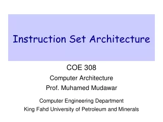
ATmega168 AVR Instruction Formats • Instructions are 2 or 4 bytes in length. • Format 1 consists of an opcode and two register operands, both of which are inputs and one is also the output of the instruction. • The ADD instruction for registers uses this format, for example. • Format 2 is also 16 bits, consisting of an additional 16 opcodes and a 5-bit register number. • This format increases the number of operations encoded in the ISA at the cost of reducing the number of instruction operands to one. • Instructions that use this format perform a unary operation, taking a single register input and writing the output of the operation to the same register. • Examples of this type of instruction include ‘‘negate’’ and ‘‘increment.’’ • Format 3 has an 8-bit unsigned immediate operand. • To accommodate such a large immediate value in a 16-bit instruction, instructions which use this encoding can have only one register operand (used as an input and output) and the register can only be R16–R31 (which limits the operand encoding to 4 bits). • Also, the number of opcode bits is cut in half, allowing only four instructions to use this format (SUBCI, SUBI, ORI, and ANDI).
ATmega168 AVR Instruction Formats Figure 5-15. The ATmega168 AVR instruction formats.
ATmega168 AVR Instruction Formats • Format 4 encodes load and store instruction, which includes a 6-bit unsigned immediate operand. • The base register is a fixed register not specified in the instruction encoding because it is implied by the load/store opcode. • Formats 5 and 6 are used for jumps and procedure calls. • The first format includes a 12-bit signed immediate value that is added to the instruction’s PC value to compute the target of the instruction. • The last format expands the offset to 22 bits, by making the AVR instruction 32 bits in size.
Addressing • An instruction must specify the address of the operands. • For example, ADD instruction requires three operands: two sources and a destination. • The ADD instruction must tell where to find the operands and where to put the result. • If memory addresses are 32-bits, the instruction requires three 32-bit addresses in addition to the opcode. • Two general methods are employed to reduce the size of the specification. • Method 1 • Operand is moved into a register if it is heavily used. • Access is faster and fewer bits are required to specify the operand • 32 registers can be specified by only 5 bits. • ADD will then requires only 15 bits for three operands instead of 96 bits if they were all in memory.
Addressing • Method 1 (cont.) • To load an operand from memory into register, first a LOAD instruction is necessary. • This will require an opcode and a memory address and the specification of the target register. • From years of experience, it is known that operands are reused a great deal, so it is worth the cost to first transfer an operand in a register. • This eliminates many memory references, reduces program size and execution time. • Method 2 • Specify one or more operands implicitly. • One way is to use a single specification for a source operand and for the destination.
Addressing • Method 2 (cont.) • A three-address ADD instruction might use the form DESTINATION = SOURCE1 + SOURCE2 • A two-address instruction might be restricted to the form REGISTER2 = REGISTER2 + SOURCE1 • In this case the contents of the REGISTER2 will not be preserved. • If the original value will be needed later, it must be first copied to another register. • The trade-off here is that two-address instructions are shorter, but they are less general. • Pentium II uses two-address ISA level instructions, whereas the UltraSPARC II uses three-address instructions. • Early computers had only a single register – accumulator • The ADD instruction always added a memory word to the accumulator, so only one operand had to be specified.
Addressing Modes • Immediate Addressing • Address part of the instruction contains the operand rather than an address or other information describing where operand is. • Advantage is that it does not require an extra memory reference to fetch the operand. • Disadvantage is that only a constant can be supplied this way. • Also the number of values is limited by the size of the field. • Direct Addressing • Full address of the operand in memory is specified. • The instruction will always access exactly the same memory location • It can be used to access global variables whose address is known at compile time. MOV R1 4
Addressing Modes • Register Addressing • Conceptually same as direct addressing but specifies a register instead of a memory location. • Many compilers put the most frequently used variables (loop index) in registers. • In load/store architectures such as OMAP4420 ARM, nearly all instructions use this addressing mode exclusively. • Register Indirect Addressing • The address of the operand is in a register. • The address used in this manner is called a pointer. • Advantage is it can reference memory without specifying full memory address in the instruction. • Also, it can use a different memory word on different executions of the instruction.
Addressing Modes • Register Indirect Addressing (cont.) • Example: Compute sum of the elements of a 1024-element one-dimensional integer array in register R1 using a loop. • Register R2 points to the first element of the array. • Register R3 points to the first address beyond the array. MOV R1,#0 ;accumulate the sum in R1, initially 0 MOV R2,#A ;R2=address of the array A MOV R3,#A+4096 ;R3=address of the first word beyond A LOOP: ADD R1,(R2) ;register indirect through R2 to get operand ADD R2,#4 ;increment r2 by one word (4 bytes) CMP R2, R3 ;are we done yet? BLT LOOP ;if R2<R3, we are not done, so continue
Addressing Modes • Register Indirect Addressing (cont.) • In the program, first three instructions use register mode for the first operand and immediate mode for the second operand. • The second instruction puts the address of A in R2, not the contents, denoted by #. • Similarly, the third instruction puts the address of the first word beyond the array in R3. • In the fourth instruction starting the loop, it uses register and register indirect mode. • In the fifth instruction it uses register and immediate mode. • In sixth instruction it uses register mode twice. • The BLT might use a memory address, but more likely it specifies the address to branch to with an 8-bit offset relative to the BLT itself.
Addressing Modes • Register Indirect Addressing (cont.) • In theory, there is another way to do this computation without using register indirect addressing. • The loop could have contained an instruction to add A to r1, such as ADD R1,A • Then on each iteration of the loop, the instruction itself could be incremented by 4, so that after one iteration it would read ADD R1,A+4 • A program that modifies itself like this is called self-modifying program. • Disadvantage of self-modifying programs is they cannot be shared among multiple processes at the same time. • Furthermore, they will not even work correctly on machines with split level 1 cache if the I-cache has no circuitry for doing writebacks.
Addressing Modes • Indexed Addressing • Addressing memory by giving a register (explicit or implicit) plus a constant offset is called indexed addressing. • Instead of a pointer into memory in a register plus a small offset in the instruction itself, we can have the memory pointer in the instruction and the small offset in the register. • Consider two one-dimensional arrays A and B of 1024 words each. • Compute Ai AND Bi and then OR these 1024 products to see if at least one nonzero pair exists. • One approach is to put address of A in one register, the address of B in a second register, and then step through them. • The other way is given next.
Addressing Modes MOV R1,#0 ;accumulate the OR in R1, initially 0 MOV R2,#0 ;R2=index, i, of current product: A[i] AND B[i] MOV R3,#4096 ;R3=first index value not to use LOOP: MOV R4,A(R2) ;R4= A[i] AND R4,B(R2) ;R4= A[i] AND B[i] OR R1,R4 ;OR all the Boolean products into R1 ADD R2,#4 ;i=i+4 (step in units of 1 word = 4 bytes) CMP R2,R3 ;are we done yet? BLT LOOP ;if R2<R3, we are not done, so continue • The four registers are as follows: • 1. R1 – Holds the accumulated OR of the Boolean product terms • 2. R2 – The index, i, that is used to step through the arrays • 3. R3 – The constant 4096, which is the lowest value of i not to use • 4. R4 - A scratch register for holding each product as it is formed
Addressing Modes • The instruction at LOOP fetches Ai into R4. • A register, R2, and a constant, the address of A are added together and used to reference memory as source • The source uses indexed mode with A as the offset and R2 as the register. • If A has the value, say, 124300, the actual machine instruction will look like this: • The first time through the loop, R2 is 0, so the memory word addressed is A0, at address 124300. • The next time through the loop, R2 is 4, so the memory word addressed is A1, at 124304. • This form requires an offset field in the instruction large enough to hold an address, although inefficient, is the best way. MOV R4 R2 124300
Addressing Modes • Based-Indexed Addressing • The memory address is computed by adding up two registers plus an (optional) offset. • One of the registers is the base and the other is the index. • In the last example, outside the loop the address of A can be put in R5 and the address of B in R6. • The LOOP instruction and its successor can be written as: • If the offsets are always 32 bits, then nothing is gained by using this mode. • In practice, machines that have this mode usually have a form with 8-bit or 16-bit offset. LOOP: MOV R4,(R2+R5) AND R4,(R2+R6)
Addressing Modes • Stack Addressing • Short machine instructions are desirable. • Zero address instructions, such as IADD are possible in conjunction with stack. • Reverse Polish Notation • The form x y + with the operator after the operands is called postfix or reverse Polish notation. • Advantages of reverse Polish notation over infix • Any formula can be expressed without parentheses • It is convenient for evaluating formulas on computers with stacks • Infix operators have precedence, which is arbitrary and undesirable • a x b + c means (a x b)+c as multiplication has higher precedence
Addressing Modes • Dijkstra’s Algorithm – converting infix into reverse Polish notation • Assume formula composed of following symbols: variables, dyadic (two-operand) operators + - * / ( ) • The ends are marked with • The train of symbols moves west. • When each car arrives at the switch, it must check if it should go directly to California or to Texas. • Cars containing variables always go directly to California and never to Texas. • Cars containing all other symbols take action according to Figure, depending on the contents of the nearest car on the Texas line and the car at the switch. • The first always goes to Texas.
Addressing Modes • Dijkstra’s Algorithm (cont.) • The car at the switch heads towards Texas • The most recent car on the Texas line turns and goes to California • Both the car at the switch and the most recent car on the Texas line are hijacked and disappear (i.e. both are deleted) • Stop. The symbols now in California represent the reverse Polish notation formula when read from left to right • Stop. An error has occurred. The original formula was not correctly balanced.
Addressing Modes • Dijkstra’s Algorithm (cont.) • After each action is taken, a new comparison is made between the car at the switch and the most recent car at last of Texas line. • The process continues until step 4 is reached. • The order of the operators in reverse Polish notation is the order in which they actually be executed during the evaluation of the expression.
Addressing Modes • Evaluation of Reverse Polish Notation Formulas • Ideal for evaluating formulas on a computer with a stack • The formula consists of n symbols, each one either an operand or an operator. • Scan the reverse Polish notation string from left to right. • When an operand is encountered, push it onto the stack. • When an operator is encountered, execute the corresponding instruction. • Example: (8+2x5)/(1+3x2-4) in reverse Polish notation is: • 8 2 5 x + 1 3 2 x + 4 - /