Download
1 / 17

E N D
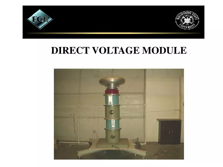
ABSTRACT The Direct Voltage Module, also known as a DC module is used for high – voltage testing. The main application of a DC Module is to determine the positive and negative flash over on high voltage components. This type of testing is necessary because DC voltage has different effects compared to AC. This type of equipment is important to high – voltage laboratories such as the High Voltage Laboratory found here at Mississippi State University.
TEAM MEMBERS: Pictured from left to right: Team Member: William Zender Faculty Advisor: Dr. Stan Grzybowski Team Leader: Trinity Baggett
MOTIVATION • MISSISSIPPI STATE UNIVERSITY’S HIGH VOLTAGE LABORATORY REQUIRES AT LEAST 525 KVDC FOR TESTING HIGH VOLTAGE EQUIPMENT • THE BUDGET WILL NOT ALLOW THE LABORATORY TO BUY A NEW MODULE
REQUIREMENTS • RIPPLE FACTOR < 5% • CURRENT LIMITATION < 2.0 Amps • CASCADING • BLEED-OFF RESISTOR • INSULATING COMPOUND
INSULATING COMPOUND • OIL INSULATION • ADVANTAGES • EASILY ACQUIRED • BETTER HEAT TRANSFER • DISADVANTAGES • ADDED WEIGHT • AGEING PROCESS REDUCES INSULATION STRENGTH • SLUDGE BUILD UP REDUCES CIRCULATION OF OIL • SF6 GAS INSULATION • ADVANTAGES • EASILY ACQUIRED • VERY LARGE DIELECTRIC STRENGTH • THERMAL STABILITY • LIGHT WEIGHT • LOW TEMPERATURE CONDENSATION
TEST RESULTS RIPPLE AMPLITUDE = .5(VMAX-VMIN) =.5(230- (-230)) = 230 MILLIVOLTS RIPPLE FACTOR = RIPPLE AMPLITUDE/VMEAN = .32% CURRENT @ 175 KVDC IS 1.5 mA. CAPACITOR VALUE = 5.7 nF RIPPLE AMPLITUDE = (I * T)/(2*C) RIPPLE FACTOR = 1.27 %
FUTURE IMPROVEMENTS • CONTROLS ALLOWING THE OUTPUT VOLTAGE TO BE VARIED VIA REMOTE CONTROL • DESIGNING AND CONSTRUCTING A DIRECT VOLTAGE MODULE THAT IS EXTREMELY SMALL • DESIGNING A DIRECT VOLTAGE MODULE CAPABLE OF PRODUCING 525 KVDC
REFERENCES R. T. Thomas, “High impulse current and voltage measurements”, Tr. IEEE IM, IM-19, 102 (1970). J. D. Craggs, J. M. Meek, “High Voltage Laboratory Techniques”, Butterworths Scientific Publications, London (1964). J. Schwab, “High Voltage Measurement Technique”, M.I.T. Press, Cambridge, Massachusetts(1972). G. W. Bowlder, “Measurement in High Voltage Test Circuits”, Pergamon Press, Oxford(1975). D. Kind, “An Introduction to High Voltage Experimental Techniques”, Friedr Vieweg & Sohn Verlagsgeselchaft mbh, West Germany(1978). M. Khalifa, “High-Voltage Engineering, Theory and Practice”, Marcel Dekker, New York, New York(1990). M. S. Naidu, V. Kamaraju, “High Voltage Engineering, Second Edition”, McGraw-Hill, New York(1995). T. J. Gallagher, A. J. Pearmain, “High Voltage Measurement, Testing and Design”, John Wiley & Sons, New York(1983). K. Denno, “High Voltage Engineering in Power Systems”, CRC Press., Boca Raton, Florida(1992)