Download
1 / 54
540 likes | 689 Views
Setting Up and Managing Switched Networks. ITS 905 Instructor: Kent Reuber, consultant for Engineering departments reuber@stanford.edu, 725-8092. Outline. Definitions Switch Models and Building Design Configuring Cisco 2900/3500 Switches Managing Switches via Web and Telnet

E N D
Setting Up and Managing Switched Networks ITS 905 Instructor: Kent Reuber, consultant for Engineering departments reuber@stanford.edu, 725-8092
Outline • Definitions • Switch Models and Building Design • Configuring Cisco 2900/3500 Switches • Managing Switches via Web and Telnet • Reference Section • Lab (Optional)
What’s a Smart Hub? • A smart hub can be configured and remotely managed. For example, ports can be shut off. • However, this doesn’t mean that it does anything smart with network traffic. It has no switching capabilities. Traffic is always forwarded to all ports. • Our most common smart hub on campus is the Asanté NetStacker. • Networking no longer recommends hubs for wiring closets. It may be OK to use small unmanaged hubs to give selected offices additional ports. Use hubs with care!
What’s a Bridge? Stanford has mostly decommissioned NAT bridges, but since switches do bridging, it’s worth discussing how these work. A bridge separates network segments into two “collision domains”, allowing both sides to support one “conversation” on each side. Each side has “bridging table”: a list of all MAC addresses on their side. Based on its lists, a bridge determines if it should keep a packet on one side, or forward it to the other. A NAT bridge will show a solid green “Status 3” light if working properly. Any other condition is an error. One common error condition is an unterminated coaxial segment. Broadcasts and Multicasts are always forwarded to both sides (or to every port in the case of a switch). If you use a sniffer on a switch port, this should be the only traffic you see.
What’s a Switch? A switch is a hub where every port acts as a bridge. Each port remembers the MAC addresses of all devices connected to it. If The switch as a whole keeps a master list of all these MAC addresses by port. If a user has a mini-hub in their office, you will see multiple MAC addresses on a switch port. A switch port periodically drops unseen addresses from its list. Pinging a host by IP address will put the corresponding MAC address back in the table (assuming the device is on). The end result of this is that network traffic is generally not repeated across all ports (unless it’s a broadcast or multicast). For example, if a computer on port 2 is sending a huge file to the server on port 8, no other ports see this traffic. Network traffic problems almost always disappear with switches. Collisions become a thing of the past.
Private Address Ranges • There are ranges of addresses that are not routed anywhere on the Internet. Any site may use these addresses for their own purpose: 10.*.*.*, 172.16.*.* – 172.32.*.*, 192.168.*.* • Devices with private addresses cannot access or be accessed by hosts outside of Stanford. That’s usually OK for switches, printers, etc. • If your network is 171.6x.y.*, your private address is probably 172.2x.y.* • For large nets, there may be only one private range. E.g, the private net associated with 171.64.52 – 55 is 172.24.52.* • You can check in Netdb or whois. Look up the Network record for your net number. Net numbers end in “0”, e.g., 171.64.20.0 • The netmask for devices on the private net is 255.255.255.0. Don’t use 172.24.1.1 for a gateway. Use a “.1” address for the specific network. (For example, use 172.24.20.1 for net 20.)
The Wonders of Spanning Tree What would happen in the following situation: Which switch would send the packet? What would happen if both switches sent a packet from one side to the other? To prevent such a problem, there is Spanning Tree Protocol. Simply put, the two bridging devices decide which one will do the bridging, and which one will enter “standby” mode. If you wish to use switches to provide redundancy in your network, you can do so. Spanning tree will force one switch to shut off that port. The primary problem of spanning tree is that it takes 20-30 seconds or more for the port of a switch to discover if it is connected to another switch. This can cause problems with many desktop computers which become impatient with the delay, assume there’s no network connection, and give an error. switch switch
Fun with Wiring (Copper)… • Twisted Pair: • Category 3: 10 Mb only, uses 2 pairs. • Category 5/5e: Required for 100Mb. Use 2 pairs for 100Mb, 4 pairs for gigabit (1000BaseT) • Two types of wiring configurations (RJ-45): • Standard (switch/hub to computer) • Crossover (switch-switch or computer-computer) • AutoMDIX: Some switches automatically chooses standard or crossover as appropriate. • 1000BaseT can use either standard or crossover between switches.
Fun with Wiring (Fiber) • Fiber can be used for speeds from 10Mb to 10Gb. • Names: 10FL, 100FX, 1000BaseSX/LX/ZX • Fiber switches do not auto-negotiate: no 10/100! • Two types of cables: • Single mode (yellow): Usually 8µm diameter fibers. Used for longer runs, equipment is more expensive. • Multimode (orange): Usually 62.5µm or 50µm. Used for shorter runs. 50µm can support longer runs. • Currently Stanford uses multimode for most applications. Gigabit will involve using more single mode for building feeds.
Fiber Connectors • ST (think “T for tube”): • 2 round ends with thin-wire style bayonet connectors. • Used on 10FL switches. By convention, Stanford uses ST for connections between buildings, even for 100FX. • SC (think “C for cube”): • 2 square ends that click into place • Used by 100Mb and gigabit equipment. Now used for fiber runs within a building at Stanford (new installations). • MT-RJ: • Small connector. Can be a little fragile. Used when you need to put lots of fiber in a small space (e.g., a switch with 24 fiber ports)
Switch Models Except for 8288, all switches are made by Cisco. Ask your network consultant for help when designing nets
What’s a GBIC? • “Gigabit Interface Converter”. Hot swappable modules for different gigabit media. • 1000BaseLX (fiber). Used mainly for runs between buildings (~550m limit on 62.5 µm multimode fiber, 5km on single mode) • 1000BaseSX (fiber). Used mainly for runs between wiring closets (~220m limit on 62.5 µm multimode, ~500m on 50µm multimode. Cannot be used with single mode). • Gigastack or “stacking GBIC” (copper). Can be used to connect switches within a rack. Note that switches in a stack can act as though they were connected with a Gigabit hub -- you *can* have collisions. Probably don’t want to use these. • 1000BaseT. Gigabit over Cat 5. For servers and/or switches. • Warning: GBICs are static sensitive. Cisco recommends using a grounding strap.
A brief interlude into IOS • Cisco Catalyst 2900-series switches use Cisco’s IOS operating system, which is the same OS used on their routers. • In this class, we cover only the basic IOS commands needed for switch configuration and basic management. • There are 5-day classes that introduce you to IOS, and then other 5-day classes offered by third parties that you take to get into some of the details. • IOS works on levels. You have to be at the right level to issue the desired command. • The most useful level is the “enable” level, from which you will be able to see your configurations and save (write) your configuration. Very similar to becoming “root” in Unix or “Administrator” in Windows. • There’s also a configuration level which is used to input new commands. • For example, to change the speed and duplex for a switch port (Cisco calls this an “interface”), you must: • Enter enable mode • Enter configuration mode • Specify the interface you want to modify (e.g., FastEthernet 0/1) • Issue the commands to change speed and duplex
IOS (Continued) The most useful IOS commands are: • en to enter enable mode (from which you do everything). When in enabled mode, a # will appear in the prompt (Switch> becomes Switch#). At each level the prompt changes (Switch(config)# or switch(config-if)# etc.) You’ll see some of this in our configuration. • Show run will show the current running configuration while Show config will show the stored configuration. The write will store the running configuration. • Config t to configure over the terminal (your current session). • Config net to configure over the network (download a configuration file from a tftp server). • Exit to go back a level (i.e. to go from config to enable level to write a configuration, control-Z will get you all the way back to the enable level) Any config changes are not saved until you issue a “write” command.
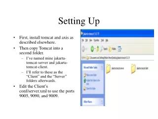
What you’ll need You’ll Need: • A laptop or desktop computer with a serial connection. • The special serial cable that comes with the switch. • A crossover cable (usually hot pink or lime green) • A network connection. Set up: • Turn AppleTalk off (if using an older PowerBook) • Create a NetDB record for the switch (you need an appropriate IP address) • Connect the serial cable (using the appropriate adapters) to the RJ-45 console port on the switch • Connect the switch, using the crossover cable, to an Ethernet connection. • Start a serial session.
The Old Way… • Do basic switch network configuration: • IP address, netmask, gateway, hostname • passwords • Download supplementary configuration file: • Stanford DNS servers, standard access lists (address ranges allowed to access the switch) • Any switch specific configuration: • Additional access lists, spanning tree settings
The New Way… • Copy a configuration file from the LNA Guide into a text editor. • Make a few changes to the configuration (address, gateway, etc.) • Paste new configuration into terminal window.
Step 1: Get a config file • Go to the LNA Guide “Hardware” section: • http://lna.stanford.edu/hardware.html • Note, this page is restricted to LNAs. • Select the link appropriate for your switch. This will open the config file in a browser window: • 24 10/100 ports (2924, 2950-24, 3524, etc.) • 48 10/100 ports (2950-48, 3540, 3550-48) • All gigabit (3508, 3550-12G, 3550-12T) • Select all this text and paste it into a text editor (e.g., Notepad in Windows, or TeachText for Mac)
Step 2: Edit the config file • The config file you’ve accessed needs to be altered. Comments will show you what you need to change. In general, change: • Switch IP address and default gateway • Switch hostname (name from NetDB) • Telnet and enable passwords • Web access list (what IP addresses can access the switch for Web management) • Portfast settings
Config file details: • Change the items in bold: enable config terminal # Replace the address below with your switch's IP address. # The netmask will probably not need to be changed. interface VLAN1 ip address 172.24.00.000 255.255.255.0 no shutdown exit # Replace with your gateway address. ip default-gateway 172.24.00.1 # Replace "SWITCH" with the name of the switch as shown in netdb hostname SWITCH
Config file details (pt. 2): • More things to change: # Replace "SEKRIT" with the "enable" password of your switch. # This password allows you to make changes. enable secret SEKRIT # Replace "SEKRIT2" with the telnet password for the switch. # We recommend that you make this different than the enable password. line vty 0 4 password SEKRIT2 exit # Uncomment the line below if you DON'T want your switch to be # running a Web server for management purposes. # #no ip http server
Config file details (pt. 3): • More things to change: # The next lines control which address ranges can manage your switches. # You should not need to change access-list 1, which is for telnet # access. ip http access-class 2 access-list 1 permit 171.64.0.0 0.3.255.255 access-list 1 permit 172.24.0.0 0.3.255.255 access-list 2 permit 171.64.20.0 0.0.0.255 # Access-class 2 is for Web management. Add any net ranges that should # be allowed to manage your switches below. The second number is # the width of the access block. For example # "access-list 1 permit 172.24.0.0 0.3.255.255” allows any device from # 172.24.0.0 through 172.27.255.255 to manage the switches. # Uncomment the line below and add your subnet(s) of choice. #access-list 2 permit 171.64.00.0 0.0.0.255
Config file details (pt. 4): • More things to change. Remove the portfast statement from any port that will connect to another switch. # The instructions below enables portfast on every 10/100 port. # We assume one of the Gigabit ports is the uplink port. # If your uplink port is on one of the 10/100 ports, # remove the "spanning-tree portfast" line for this port. # If this is a distribution switch, remove the "spanning-tree portfast" # lines from *EVERY* port that links one switch with another. # In other words, portfast is usually a good thing for ports that # connect to computers, printers, etc., but *NOT* a good thing for # links that connect switches to one another. interface FastEthernet0/1 spanning-tree portfast interface FastEthernet0/2 spanning-tree portfast
Step 3: Paste • Copy the modified config file in the text editor. • Paste into the terminal window. • **Done** (Note: we have seen instances where the paste operation fails mid-way through. This is probably dependant on the terminal software used. If it does fail, paste again from the point where the failure occurs. You may want to try pasting the config file in 2-3 smaller “chunks”.)
Cisco Web Interface • Log in to the switch by its name or IP number through Netscape 4 + or IE 4+. You should use a PC — the Cisco Web management software works poorly (if at all) from Macs. • The quality of the Web interface varies with the software version of the switch and the browser version. In general, Networking only uses the Telnet interface, because it’s much more reliable and can be accessed from any machine. • However, the Web interface is the easiest way of doing switch software upgrades. • When you connect via a browser, you will see a username/password dialog. Put in the enable password. Leave the name area blank. • Click on “Web Console.” • Note how each active port looks just like it would if you were looking at the switch. Click the “Mode” button to cycle through the modes just like you were clicking on the “Mode” button on an actual switch. • Note: Don’t the web interface and a telnet connection at the same time-- some of your changes may not be written to the config file.
Cisco 2900 Web Interfaces • Generation 1: • Long narrow menu bar (not hierarchical) • Generation 2: • Shorter, fatter menu bar with “popup” action • Generation 3: • Requires Java plugin (no Mac/Linux version!) • This is the only version for the 3500
Common Switch Management Tasks • Enabling/Disabling Ports: e.g., a hacked machine is spewing packets and we want to shut if off. • Turning on PortFast: Bypasses the ~30 sec delay caused by spanning tree when devices are booting. • Fixes “Your AppleTalk network is now available” warning • Fixes some problems with Ethernet-LocalTalk bridges and any host having problems getting an address via DHCP. • Labeling Ports. Helps you keep straight who’s plugged into each port. But, you may prefer spreadsheets/database. • Forcing port speed/duplex: some devices don’t auto-negotiate well. • Important note: Saving changes is a separate step!
Port Commands • Generation 1: • PortFast: “STP” menu. Check/uncheck boxes. • “Port” menu for other functions • Generation 2: • PortFast: “Device” menu, “Spanning Tree Protocol” item. Select VLAN from the list (usually there’s just 1), then click button “Modify STP parameters”. Check/uncheck boxes. • “Port” menu, “Port Configuration” item for other functions • Generation 3: • “Port” menu, “Port Configuration” item for everything. • A new window will open. Click the row of the port you want to modify and click the “modify” button.
Saving Configuration Changes • Changes via Web interface requires 2 steps • “Apply” changes on the screen of interest • “Save” the change on the “System” menu • Location of “Save” command • Generation 1: “System” menu, “Save Configuration” button • Generation 2: “System” menu, “System Configuration” item, “Save Configuration” button • Generation 3: “System” menu, “Save Configuration” item
Telnet interface • The telnet syntax is exactly the same as the format of the configuration file • Telnet to the switch and get into enable mode. Type“show run” command to see the current config. (“show config” shows the saved config) • Notice the lines that look like: • interface FastEthernet0/1 • This is where port specific information goes • At any point you can type “?”. IOS will show you what the possible values are.
Telnet interface (cont) • Example: switch#config t Enter configuration commands, one per line. End with CNTL/Z. switch(config)#interface fastethernet 0/1 switch(config-if)#? • (There are many more commands. I’ve deleted most of them for brevity.) Interface configuration commands: duplex Configure duplex operation. exit Exit from interface configuration mode spanning-tree Spanning Tree Subsystem speed Configure speed operation. switch(config-if)#speed ? 10 Force 10 Mbps operation 100 Force 100 Mbps operation auto Enable AUTO speed configuration
Telnet interface (cont.) switch(config-if)#duplex ? auto Enable AUTO duplex configuration full Force full duplex operation half Force half-duplex operation switch(config-if)#spanning-tree ? cost Change an interface's spanning tree path cost port-priority Change an interface's spanning tree priority portfast Allow a change from blocking to forwarding vlan VLAN Switch Spanning Trees • Full example: switch(config)#interface fastethernet 0/1 switch(config-if)# Speed 100 switch(config-if)# Duplex full switch(config-if)# Spantree portfast switch(config-if)# ctrl-Z switch#write
Hunting Down Bad Devices • Look at the MAC address table to find specific device and shut down a port. (Caution: a device on another switch will be listed as being on the port connecting the switches. You don’t want to shut this port off!) • Switch>enable • Switch#show mac-address-table • Dynamic Address Count: 63 • Secure Address Count: 0 • Static Address (User-defined) Count: 12 • System Self Address Count: 27 • Total MAC addresses: 102 • Maximum MAC addresses: 8192 • Non-static Address Table: • Destination Address Address Type VLAN Destination Port • ------------------- ------------ ---- -------------------- • 0000.0c07.ac14 Dynamic 1 FastEthernet0/24 • 0000.0c14.257b Dynamic 1 FastEthernet0/24 • 0000.1b16.765a Dynamic 1 FastEthernet0/24 • 0003.933e.b76e Dynamic 1 FastEthernet0/24
Hunting, Part 2 • When hunting, you probably want to search for a specific address rather than looking at the whole table. • Commands aren’t the same on all switches. Also, the format of the MAC address changes! • Switches with IOS (2900, 3500 series): • Show mac-address-table address xxxx.xxxx.xxxx • Switches with CatOS (4000, 5000, 6000 series) • Show cam xx-xx-xx-xx-xx-xx
Hunting, pt. 3 • Finding adjacent switch with Cisco Discovery Protocol (CDP only works with Cisco): • nw-test-2950#show cdp neighbors • Capability Codes: R - Router, T - Trans Bridge, B - Source Route Bridge • S - Switch, H - Host, I - IGMP, r - Repeater • Device ID Local Intrfce Holdtme Capability Platform Port ID • Pine-Pyramid-1.stFas 0/24 130 S WS-C2924C-Fas 0/10 • Adjacent switch is “pine-pyramid-1” (.stanford.edu is truncated) • Documenting your network (what switches/ports connect to each other) may be more useful and faster!
Hunting, pt. 4 • Once you find a bad device, you may want to shut down the port: • nw-test-2950#config t • Enter configuration commands, one per line. End with CNTL/Z. • nw-test-2950(config)#interface fastethernet 0/1 • nw-test-2950(config-if)#shutdown • nw-test-2950(config-if)#exit • nw-test-2950(config)#exit • Make a note of what ports you shut down! • Use “no shutdown” command to re-enable the port.
That’s It!! • Please give us feedback: fill out the feedback (yellow) forms. • We add and remove content from our classes all the time. Please let us know how we can improve our courses! • What do you want to see more of? • What do you want less of? • Please feel free to send me comments • reuber@stanford.edu • (650) 725-8092
NAT Bridge Status Look at http://whatsup.stanford.edu. Login as “guest” with no password. Click on NAT Bridges, or Building Entrance Devices, look for your bridge. If it’s in a green field, you’re fine. If it’s in a red field, we’ve been notified. Network Ops staff are paged when bridges die. Please let us know (3-3909) if you need to turn one off or remove one. If your bridge isn’t in the list, let us know. If you need a replacement bridge, your Network Consultant will configure it for you. Hint: If you can get to the bridge, look for a constant light under Status #3. Any combination of lights other than just one light under 3 is a problem. If we aren’t already out there fixing it, let us know.
Cisco Catalyst 1900 Switches You’ll Need: • A serial cable. • A converter to use your serial cable with the DB9 male port on the back of the hub (for older 1900’s) or the special cable that comes with the switch. • A laptop or desktop computer with a serial connection. • To turn AppleTalk off (if using older PowerBook) Set up: • Connect the serial cable (using the appropriate adapters) to the RJ-45 Console Port (or DB9 Console Port) • Have the IP number ready, and a label to put on the switch. • Launch your terminal emulation program of choice (Mac- or PC-Samson are recommended) • Start a serial session. • Hit return a couple of times.
Catalyst 1900 Set up (Continued) • If fresh from the factory, you’ll have an initial IP configuration option. Type I (or, for an older switch, N then I) Type I again, enter the IP number. Type S enter an appropriate subnet mask (public: 255.255.0.0, private: 255.255.255.0) Type G enter an appropriate gateway (e.g. 171.64.1.1 or 172.24.xx.1) Type M enter a 171.64.7.55, 77 or 99. Type N and choose another DNS computer. Type D enter stanford.edu (The “M,” “N,” and “D” choices aren’t on the older 1900’s) • Type X to finish IP configuration, X again to get to the main menu. Type C for console settings, and M to set a password. Type X until you’ve exited the console, type Y to really exit.