Download
1 / 17
170 likes | 263 Views
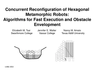
Choosing Good Paths for Fast Distributed Reconfiguration of Hexagonal Metamorphic Robots. Jennifer E. Walter Elizabeth M. Tsai Nancy M. Amato Vassar College Swarthmore College Texas A&M University. Metamorphic Robotic Systems.

E N D
Choosing Good Paths for Fast Distributed Reconfiguration of Hexagonal Metamorphic Robots Jennifer E. Walter Elizabeth M. Tsai Nancy M. Amato Vassar College Swarthmore College Texas A&M University
Metamorphic Robotic Systems • We model robots like those developed by Chirikjian (ICRA94) • System composed of masses or clusters of robots (modules) Metamorphic modules are... • 1) Uniform in structure and capability • homogenous with regular symmetry • modules fit together with minimal gaps • 2) Individually mobile to allow system to change shape • modules can connect, disconnect, and move over adjacent modules
2 3 1 Step 4: move 2 CCW Step 3: move 2 CCW Step 2: move 3 CCW Step 1: move 3 CCW 2 3 3 3 3 2 1 1 1 1 2 2 Step 5: move 2 CCW time Motion Planning Problem Statement Determine sequence of moves to reconfigure modules from an initial configuration I to a final configuration G • | I | = |G| = n (number of modules in system) • any module can fill any cell in G G I 1 3 2 Additionally, we want as many modules as possible to move concurrently.
S S S S S Our Approach Centralized motion plan for efficient concurrent reconfiguration that avoids deadlock and collision without message passing 2D hexagonal modules move by... • A combination of rotation and changing joint angles, disconnecting and connecting sides at appropriate times • Modules “crawl” over unmoving neighbors (Sfor substrate) A chain of unmoving modules that other modules move across during reconfiguration is called the substrate path.
I and G initially intersect in some goal cell in the westernmost column of G General Reconfiguration Strategy Determine if G is admissible. If not, report failure. 2) Select an admissible substrate path that approximately bisects the goal configuration. 3) Fill in the goal portion of the substrate path first, then fill in rest of goal cells above and below substrate path.
Admissible Goal Configurations • Pockets like this occur frequently in systems of hexagonal modules due to module shape. • Informally, an admissible substrate pathis a chain of modules that • allows traversal on both sides without collision or deadlock and • spans G Admissible G • G is an admissible goal configuration if it contains an admissible substrate path. Inadmissible G
Fast Parallel Reconfiguration • Fastest reconfiguration occurs when the substrate path… • ...is a straight chain or a chain with a single obtuse angle bend • why? Because modules can move with minimal separation, rotating in alternate directions. • ... bisects G • why? Because after the substrate path is filled in, modules can fill in both top and bottom of G simultaneously, without possibility of collision.
Direct some of the edges of Gso that all “goal-spanning • paths” can be traversed, from west to east. • Edges that are unsuitable for inclusion in an admissible substrate path are not directed H Converting G to directed graph H Goal cells blue, non-goal cells gray
v = 10 v = 1 v = 0 Weighting Vertices • Our graph traversal algorithm finds all goal-spanning paths in H. During execution, the vertices are weighted as shown below: v with incoming edge in different direction than parent’s incoming edge v with incoming edge in same direction as parent’s incoming edge v with an incoming vertical edge
F D A E B C F G D A E B C Example Graph Traversal with Path Weighting F F D G A D G A E 1 B E 0 B 0 1 0 C C 0 cost of A – B – C – E – G = 1 Root marked F D G G A 3 E 1 B 0 0 2 0 0 C Backtracking to vertex B. E and G are unmarked. C remains marked since D hasn’t been visited cost of A – B – D – E – G = 3 F 1 D G A 1 2 1 E 0 0 B 0 0 C Backtracking to vertex D. G is unmarked. E remains marked since F hasn’t been visited cost of A – B – D – F – G = 2
Selecting The Best Substrate Path For each goal-spanning path of H, a path cost is evaluated. Candidate paths in H are considered in the following order: 1)Paths with cost 0 ( straight ) or cost 1 ( single bend ) that equally (or almost equally) bisect H 2) Higher cost paths that equally (or almost equally) bisect H Selected Selected Not selected Not selected Cost 5 path that doesn’t bisect H Cost 0 path that equally bisects H Cost 1 path that does not equally bisect H Cost 2 path that partially bisects H
Summary • Our method for finding the best admissible substrate path for reconfiguration is • summarized as follows: • 1) Convert G to an acyclic graph, H, and direct the edges • 2) Use the graph traversal algorithm to • traverse all paths and determine path costs in H, and • choose froma set of lowest cost paths a substrate path that most equally divides H Examples of good substrate paths found:
chosen path other paths 50 40 30 20 10 0 square bridge buttress Simulation Results The effectiveness of our strategy to choose the “best” path was verified using a simulator to count the number of rounds needed to reconfigure different goal shapes. Rounds of Reconfiguration by Goal Shape # of rounds
How to check for obstacle admissibility For each obstacle cell on the perimeter of the obstacle… …for each side of the cell that is a goal cell… …check two and three cells over for another goal cell (i.e. pocket of size 1 or 2) Reconfiguration with a Single Obstacle We consider the presence of a single obstacle in the environment that must… • be enclosed completely inside the goal • have an admissible surface What is an admissible surface? • an admissible substrate path – i.e. all pockets must have clearance of at least three cells Obstacle with pocket of size 1
Determining Substrate Path with a Single Obstacle • Original Idea • Direct the edges west of the goal to determine the “entrance” point for the path • Direct the edges inside the goal to determine the “exit” point for the path • Direct the edges east of the goal,going out of the exit point • Form the final substrate path by concatenating the above path segments But wait! We have a problem! Filled goal cell Filled substrate path cell • Small pockets that modules can’t crawl through can form where the substrate path meets the obstacle • These pockets are a result of the East-To-West filling-in strategy Pocket formed by obstacle and filled-in goal cells
Repairing the Obstacle To remedy the “pocket problem,” we “repair” the obstacle surface. • Why? • want to avoid modules getting trapped when filling in from east to west • want modules to crawl over obstacle surface as a substrate path during reconfiguration • How do we “repair” an obstacle? • form a cone shape with the eastern-most column of the obstacle as its base • fill in this cone from south to north, and from west to east Unrepaired obstacle Repaired obstacle
Future Work • Change existing simulation to include internal and external obstacles. • 2. Algorithmic work: • asynchronous reconfiguration algorithms. • procedures for deadlock and collision resolution. • “complete” reconfiguration, from arbitrary initial to arbitrary goal.