Download
1 / 27
270 likes | 354 Views
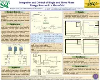
Joint Design-Time and Post-Silicon Optimization for Analog Circuits: A Case Study Using High-Speed Transmitter. Yiyu Shi , W ei Yao, Lei He , and Sudhakar Pamarti Electrical Engineering Dept., UCLA Speakers: Edward Kao and Scott Fukushima. Outline. Introduction Design-Time Optimization

E N D
Joint Design-Time and Post-Silicon Optimization for Analog Circuits:A Case Study Using High-Speed Transmitter Yiyu Shi,Wei Yao, Lei He, and Sudhakar Pamarti Electrical Engineering Dept., UCLA Speakers: Edward Kao and Scott Fukushima
Outline • Introduction • Design-Time Optimization • Post-Silicon Tuning and Joint Optimization • Optimization Framework • Experimental Results • Conclusions
Problem Statement • Goal • To maximize parametric yield for analog circuits • Reasons for Concern • Analog circuits are highly sensitive to process variation • Process variation causes problems for parametric yield and becomes worse with technology scaling • Techniques for maximize parametric yield • Design-time optimization • Post-silicon tuning
Existing Work • Design-time optimization • System-level [Stojanovic:CICC’03] • System-level and circuit-level co-design [Sredojevic:ICCAD’08] • Device-level • Transistor sizing and layout optimization [Pelgrom:JSSC’89] • Post-silicon tuning • Tunable amplifier [Kaya:TCASII’07] • Programmable capacitor array for filter, ADC [Huang:JSSC’01] • Transistor finger selection to reduce mismatch [Li:ICCAD’08] • A lot more adaptive design for analog/mixed-signal circuit … First yield-driven circuit design technique that considers both post-silicon tuning along with design time optimization
Adaptive / Tunable Circuits • Tunable circuits with negative feedback loop to compensate process variation • Traditional corner-based design methodology makes sure the circuit satisfies the design spec in all process corners • Circuit tunability does not comes for free • Yield-driven optimization is required to prevent over-design
Joint Design-Time and Post-Silicon Optimization • Use high speed link transmitter design as an example • Proposed goal • Maximize yield • Yield is defined by BER • Satisfy power and area constraints • Optimization framework • Build model for analog building blocks from SPICE • Include Vt variation and consider tuning circuit cost • Use SPICE-characterized cells as building units • Combine branch-and-bound and gradient-ascent algorithm • Effectively find the global optimum solution
Outline • Introduction • Design-Time Optimization • Post-Silicon Tuning and Joint Optimization • Optimization Framework • Experimental Results • Conclusions
High-Speed Serial Link Example • Consider the transmitter pre-emphasis filter • Combats inter-symbol interference (ISI) • Plays an important role in system performance • Consumes most power at transmitter
Transmission Environment • Channel Attenuation • Dispersion • Reflection • Impedance mismatch • Inter-symbol interference • Band-limited channel • Crosstalk • Capacitive or Inductive coupling • Other random noises • ex: circuit thermal noise
Transmitter Design Pre-emphasis filter Last stage of the pre-driver Pre-filter the pulse with the inverse of the channel ai: input symbol bi: transmitter output Wj: filter coefficient Other stages of the pre-driver Sizing is according to logic effort
Transmitter Design (cont’d) • LMS algorithm is used for optimal filter coefficients given the number of taps n • Large transistor parasitic capacitance exists • Considered as part of the channel • Transistor sizing is done through parallel connected unit cells • Unit cells α are pre-characterized through simulation • Output swing constraint is applied to make sure correct operation region • Get rid of SPICE simulation during optimization
BER = V2 Performance Metric Channel Reception Transmission 010010 010010 Modulation Demodulation • Error Vector Magnitude (EVM) • Bit Error Rate (BER) I Error in the received symbol 2 e V2 1 V1 e = - V1 Ne = Number of errors R = Data rate t = Test time Q R×t > 1015 !!
Performance Metric (cont’d) • The relation between EVM and BER can be obtained through simulation • Monotonic • Highly correlated • EVM can be measured efficiently with far less data • ai: input symbol • bj: transmitter output • pj:: channel response • ri: received data • M: total number of data < 104
Outline • Introduction • Design-Time Optimization • Post-Silicon Tuning and Joint Optimization • Optimization Framework • Experimental Results • Conclusions
Process Variation • Threshold voltage variation • Doping fluctuations • Short channel device • Channel length variation also causes Vth variation • Becomes dominant in the next few technology generations • Pre-emphasis filter coefficients • Implemented as CMOS current sources • Vth Variation induces drain current mismatch • Assume 10% variation in Vth • 30% variation in power • BER varies in several order of magnitude
Post-Silicon Tuning through DAC • Current-division DAC is commonly used to combat process variation • Two design parameters • LSB size ( ): minimum step during digital-to-analog conversion • Resolution (β): number of bits used
Both power and performance variations are reduced significantly Given the same design Tuning circuits actually bring extra costs Area Larger parasitic → performance downgrade Power and Performance Variation (a) Without Tuning (b) With Tuning
Problem Formulation • Where • , e random variable
Outline • Introduction • Design-Time Optimization • Post-Silicon Tuning and Joint Optimization • Optimization Framework • Experimental Results • Conclusions
Yield vs. Power and Area • 3000 Monte Carlo runs over different unit cell design α, resolution β, and LSB size • Significant improvement can be expected • Solution space surface is rough and many local maxima exists • Discrete problem with non-convex objective and constraints
Branch and Bound with Gradient Ascent Method • Use gradient ascent method to find the local maxima • Sequentially take steps in the direction proportional to the gradient. • Bound estimation • Remove the area and power constraints • Use LMS algorithm to find the optimal coefficients • Results in best possible performance • Basic idea: • Partition the solution space by LSB size ( ) and unit cell type (α) • Develop a bound on the performance • Discard (fathom) if bound worse than the current best solution
Outline • Introduction • Design-Time Optimization • Post-Silicon Tuning and Joint Optimization • Optimization Framework • Experimental Results • Conclusions
BER Distribution Comparison • Two extreme cases • Without tuning circuit • All resources are used for filter design • Unavoidable large variation • One tap filter • All resources are used for DAC • Has extreme small variance but suffers severe ISI • Manually design • Assume LSB size is equal for each tap • Good balance between above two extreme cases • Our algorithm • Provides better solution
Experiment Results • Yield comparison for different constraints vt variation area Improve the yield by up to 47% power
Outline • Introduction • Design-Time Optimization • Post-Silicon Tuning and Joint Optimization • Optimization Framework • Experimental Results • Conclusions
Conclusions • Use high speed link transmitter design as an example • propose to maximize BER yield subject to power and area constraints. • Build model for analog building blocks from SPICE and Include Vt variation with the consideration of tuning circuit cost • Combine branch-and-bound and gradient-ascent algorithm • Effectively find the global optimum • Experiments show that, compared to manual design, joint design-time and post-silicon optimization can improve the yield by up to 47% • Future work • Consider the impact of clock • Optimize for the whole system, including receiver and clock circuitry