Download
1 / 32
360 likes | 473 Views
FPGA Design Techniques. Objectives. Increase design performance by duplicating flip-flops Increase design performance by adding pipeline stages Increase board performance by using I/O flip-flops Build reliable synchronization circuits. After completing this module, you will be able to:.

E N D
FPGA Design Techniques This material exempt per Department of Commerce license exception TSU
Objectives • Increase design performance by duplicating flip-flops • Increase design performance by adding pipeline stages • Increase board performance by using I/O flip-flops • Build reliable synchronization circuits After completing this module, you will be able to:
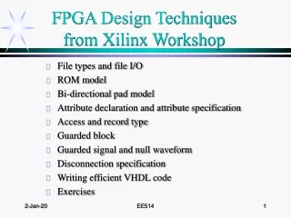
Outline • Duplicating Flip-Flops • Pipelining • I/O Flip-Flops • Synchronization Circuits • Summary
Duplicating Flip-Flops • High-fanout nets can be slow and hard to route • Duplicating flip-flops can fix both problems • Reduced fanout shortens net delays • Each flip-flop can fanout to a different physical region of the chip to reduce routing congestion • Design trade-offs • Gain routability and performance • Increase design area • Increase fanout of other nets fn1 D Q fn1 D Q fn1 D Q
Duplicating Flip-Flops Example The source flip-flop drives two register banks constrained to different regions of the chip • The source flip-flop and pad are not constrained • PERIOD = 5 ns timing constraint • Implemented with default options • Longest path = 6.806 ns • Fails to meet timing constraint
Duplicating Flip-Flops Example The source flip-flop has been duplicated • Each flip-flop drives a region of the chip • Each flip-flop can be placed closer to the register that it is driving • Shorter routing delays • Longest path = 4.666 ns • Meets timing constraint
Tips on Duplicating Flip-Flops • Name duplicated flip-flops _a, _b; NOT _1, _2 • Numbered flip-flops are mapped into the same slice by default • Duplicated flip-flops should be separated • Especially if the loads are spread across the chip • Explicitly create duplicate flip-flops in your HDL code • Most synthesis tools have automatic fanout-control features • However, they do not always pick the best division of loads • Also, duplicated flip-flops will be named _1, _2 • Many synthesis tools will optimize-out duplicated flip-flops • Set your synthesis tool to keep redundant logic • Do not duplicate flip-flops that are sourced by asynchronous signals • Synchronize the signal first • Feed the synchronized signal to multiple flip-flops
Outline • Duplicating Flip-Flops • Pipelining • I/O Flip-Flops • Synchronization Circuits • Summary
two logic levels one level one level Pipelining Concept Inserting flip-flops into a data path increases performance fMAX = n MHz D Q D Q fMAX 2n MHz D Q D Q D Q Reduces the number of logic levels (LUTs) between flip-flops
Pipelining Considerations • Are enough flip-flops available? • Refer to the MAP Report • In general, you will not run out of flip-flops • Are there multiple logic levels between flip-flops? • If there is only one logic level between flip-flops, pipelining will not improve performance • Refer to the Post-Map Static Timing Report or Post-Place & Route Static Timing Report • Can the system tolerate latency?
Latency in Pipelines • Each pipeline stage adds one clock cycle of delay before the first output will be available • Also called “filling the pipeline” • After the pipeline is filled, a new output is available every clock cycle
LUT D Q Q D LUT LUT SOURCE_FFS DEST_FF LUT Pipelining Example Circuit before pipelining • Original circuit • Two logic levels between SOURCE_FFS and DEST_FF • fMAX = ~233 MHz
D Q LUT D Q D Q LUT D Q LUT SOURCE_FFS DEST_FF D Q LUT PIPE_FFS Pipelining Example Circuit after pipelining • Pipelined circuit • One logic level between each set of flip-flops • fMAX = ~385 MHz
Review Questions • Given the original circuit, what is wrong with the pipelined circuit? • How can the problem be corrected? Pipelined Circuit Original Circuit
Answers • What is wrong with the pipelined circuit? • Latency mismatch • Older data is mixed with newer data • Circuit output is incorrect • How can the problem be corrected? • Add a flip-flop on SELECT • All data inputs now experience the same amount of latency
Outline • Duplicating Flip-Flops • Pipelining • I/O Flip-Flops • Synchronization Circuits • Summary
I/O Flip-Flop Overview • Each I/O block in the Virtex™-II Pro device contains six flip-flops • IN FF on the input, OUT FF on the output, EN FF on the 3-state enable* • Single data rate or double data rate support • I/O flip-flops provide guaranteed setup, hold, and clock-to-out times when the clock signal comes from a BUFG
Accessing I/O Flip-Flops • During synthesis • Timing-driven synthesis can force flip-flops into Input/Output Blocks (IOBs) • Some tools support attributes or synthesis directives to mark flip-flops for placement in an IOB • Xilinx Constraint Editor • Select the Misc tab and specify registers that should be placed into IOBs • You need to know the instance name for each register • During the MAP phase of implementation • In the Map Properties dialog box, the Pack I/O Registers/Latches into IOBs option is selected by default • Timing-driven packing will also move registers into IOBs for critical paths • Check the MAP Report to confirm that IOB flip-flops have been used • IOB Properties section
Outline • Duplicating Flip-Flops • Pipelining • I/O Flip-Flops • Synchronization Circuits • Summary
Synchronization Circuits • What is a synchronization circuit? • Captures an asynchronous input signal and outputs it on a clock edge • Why do you need synchronization circuits? • To prevent setup and hold time violations • To ensure a more reliable design • When do you need synchronization circuits? • Signals cross between unrelated clock domains • Between related clock domains, relative PERIOD constraints are sufficient • Chip inputs that are asynchronous
Setup and Hold Time Violations • Violations occur when the flip-flop input changes too close to a clock edge • Three possible results: • Flip-flop clocks in an old data value • Flip-flop clocks in a new data value • Flip-flop output becomes metastable
Metastability • Flip-flop output enters a transitory state • Neither a valid 0 nor a valid 1 • Can be interpreted as 0 by some loads and as 1 by others • Remains in this state for an unpredictable length of time before settling to a valid 0 or 1 • Due to a statistical nature, the occurrence of metastable events can only be reduced, not eliminated • Mean Time Between Failure (MTBF) is exponentially related to the length of time the flip-flop is given to recover • A few extra ns of recovery time can dramatically reduce the chances of a metastable event • The circuits shown in this section allow a full clock cycle for metastable recovery
Synchronization Circuit 1 Use when input pulses will always be at least one clock period wide • The “extra” flip-flops guard against metastability Guards against metastability Synchronized signal Asynchronous input D Q D Q FF1 FF2 CLK
Synchronization Circuit 2 Use when input pulses may be less than one clock period wide • FF1 captures short pulses • FF2 and FF3 act in the same way as the Synchronization 1 circuit VCC Guards against metastability Synchronized signal D Q D Q Q D FF1 FF2 FF3 Asynchronous input CLR CLK Prevents FF1 from being reset if the input to the circuit is still HIGH
D Q CE One-shot enable D Q D Q FF1 FF2 D Q Synchronized bus inputs D Q CLK Sync_Reg n bit bus D Q Capturing a Bus Use when input pulses must be at least one CLK period wide • First, the data bus is registered by the asynchronous clock. • Second, the one-shot enable (synchronized to CLK) signals to the internal circuit that data is captured (via CE). Asynchronous input CLK Leading edge detector Circuit 1
VCC One-shot enable Q D Q D Q Asynchronous Input CLK FF2 FF3 CLK D D Q FF1 Synchronized bus inputs CE CLR n bit bus Sync_Reg D Q Capturing a Bus Use when Input pulses may be less than one CLK period wide • First, the data bus is registered by the asynchronous clock. • Second, the one-shot enable (synchronized to CLK) signals to the internal circuit that data is captured (via CE). Leading edge detector Circuit 2
FIFO16 DI DO RAMB16 CORE RDCOUNT waddr raddr WRCOUNT Write Pointer Read Pointer mem_wen mem_ren oe Status Flag Logic WRCLK RDCLK WREN RDEN RESET FULL AFULL EMPTY RDERR WRERR AEMPTY Synchronization Circuit 3 • Use a FIFO to cross domains
Outline • Duplicating Flip-Flops • Pipelining • I/O Flip-Flops • Synchronization Circuits • Summary
Review Questions • High fanout is one reason to duplicate a flip-flop. What is another reason? • Provide an example of when you do not need to resynchronize a signal that crosses between clock domains • What is the purpose of the “extra” flip-flop in the synchronization circuits shown in this module?
Answers • High fanout is one reason to duplicate a flip-flop. What is another reason? • Loads are divided among multiple locations on the chip • Provide an example of when you do not need to resynchronize a signal that crosses between clock domains • Well-defined phase relationship between the clocks • Example: Clocks are the same frequency, 180 degrees out of phase • Use related PERIOD constraints to ensure that datapaths will meet timing • What is the purpose of the “extra” flip-flop in the synchronization circuits shown in this module? • To allow the first flip-flop time to recover from metastability
Summary • You can increase circuit performance by: • Duplicating flip-flops • Adding pipeline stages • Using I/O flip-flops • Some trade-offs • Duplicating flip-flops increases circuit area • Pipelining introduces latency and increases circuit area • Synchronization circuits increase reliability
Where Can I Learn More? • User Guides: www.xilinx.com Documentation User Guides • Switching Characteristics • Detailed Functional Description Input/Output Blocks (IOBs) • Application Notes: www.xilinx.com Documentation Application Notes • XAPP094: Metastability Recovery • XAPP225: Data-to-Clock Phase Alignment