Download
1 / 18
180 likes | 730 Views
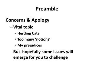
802.11ac Preamble. Date: 2010-07-13. Authors: . Slide 1. Authors (continued): . Slide 2. Background & Context. Many elements of 11ac Preamble design have been extensively debated since the IEEE Nov 2009 meeting: Preamble Discussions (09/1174r0)

E N D
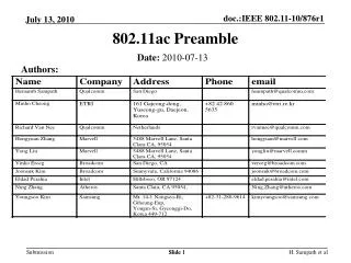
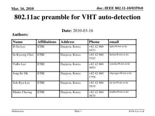
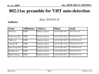
802.11ac Preamble Date:2010-07-13 Authors: Slide 1 H. Sampath et al
Authors (continued): Slide 2 H. Sampath et al
Background & Context • Many elements of 11ac Preamble design have been extensively debated since the IEEE Nov 2009 meeting: • Preamble Discussions (09/1174r0) • Auto-detection and spoofing (10/70r1- 10/70r5) • VHT-SIGA and SIGB signaling (10/70r1- 10/70r5, 0382r0-r1) • SIGB Length field & CRC in Service field (0358r0 –r1) • L-SIG based 11ac packet length indication (0534r0-r2, 772r0) • Short GI packet duration signaling (772r0) • Frame Padding to support SIGA/B signaling (0064r0-r5) • This presentation harmonizes these concepts into a unified compromise Preamble proposal. H. Sampath et al.
Abstract • The harmonized preamble proposal has the following features: • Preamble structure to enable auto-detection and spoofing. • Harmonized VHT-SIGA and SIGB signaling mechanism. • 11ac Packet Length indication • Frame Padding to complement the Preamble design H. Sampath et al.
Preamble Structure – I • The preamble structure is based on 10/70r5. • The main idea of the Preamble structure is to enable spoofing and auto-detection as follows: • Use L-SIG spoofing for both 11a and 11n receivers: • Similar to 11n spoofing for 11a/g receivers. • Rate=6Mbps, Length/Rate indicates duration. • Mode detection • First symbol of VHT-SIG-A is BPSK • 11n receiver will treat the packet as 11a packet • Second symbol of VHT-SIG-A is 90-deg rotated BPSK (QBPSK) • Allows VHT devices to discriminate 11ac packets from 11a packets H. Sampath et al
Preamble Structure - II Rate=6Mbps Length determined by T 2 symbols 1 symbol L-STF L-LTF L-SIG VHTSIGA VHT-STF VHT-LTFs VHTSIGB VHTData T VHT auto-detection Single Unified Preamble format for SU and MU
VHTSIG Field Structure • Both SU and MU contain VHTSIGA and VHTSIGB. • VHTSIGA and VHTSIGB use BPSK modulation and Long GI. • For MU: • VHTSIGA contains the “common” bits for all clients. • VHTSIGB contains user-specific information (e.g. modulation and coding rate) and is spatially multiplexed for different clients. • Max number of MU users: 4 • See 10/70r5 for more details H. Sampath et al
VHT SIG-A bit allocation Note: MCS for SU case in VHT-SIG-A to allow for 11n-like receiver implementation
SIG-A Short GI Packet Duration Signaling • LSIG Packet Length Indication • Length field in L-SIG already has sufficient information to signal the duration of a VHT packet • Do not need to indicate VHT packet duration again in VHT-SIG A • Instead use 2 bits for short GI indication in SIG A • One bit for long/short GI indication • One bit for short GI packet length ambiguity mitigation • See 0772r0 for more details.
VHT-SIGB Bit Allocation • VHT-SIGB Allocation (20/40/80 MHz) • Note: DWORD Length allows receivers to shut-off PHY processing after receiving useful data and save power. • * Additional bits to accommodate large packet sizes in 5.46ms (max packet duration in LSIG) • **Additional bits for 40 MHz and 80 MHz explained in next slide • 160 MHz repeats the 80 MHz VHT-SIG-B twice in frequency. H. Sampath et al
VHT-SIGB Modulation • Use BPSK Modulation for SIGB. • In 20 MHz mode, 26 bits are available in VHT-SIG-B. • For higher BWs, additional bits are available due to extra tones • In 40 MHz, we get 27 bits. • In 80 MHz, we get 29 bits • For 40/80/160 MHz, repeat bits including tail bits. • Provides easy way for receiver to get processing gain by averaging repeated soft values at the decoder input H. Sampath et al
VHT SIGB CRC in SERVICE Field • Transmitter shall include SIGB CRC in SERVICE field: • Transmitter shall compute 8-bit CRC based on SIGB and insert this 8-bit CRC in 8 MSBs of the SERVICE field. • Transmitter will not include scrambler seed in computation of CRC bits. • The resulting SERVICE field and PSDU shall be scrambled, as in 11n. • Explanatory Note: CRC achieves protection of the scrambler init field.This is because any error in the scrambler init field will result in a corrupted CRC field after descrambling. The check of the CRCfield against the contents of SIG-B will then fail. VHT-SIGB Service Field 20 bits in 20MHz *21 (40MHz) / 23(80MHz) bits Tail (6bit) Scrambler Seed (7bit) Rsvd (1bit) CRC (8bit) H. Sampath et al
Tx and Rx Rules on SIGB-Length • The receiver shall rely on LSIG-LENGTH duration (# of symbols) to set CCA deferral. • The number of octets implied by VHTSIGB length shall not be more than 3 octets longer than the number of octets implied by LSIG-LENGTH and VHT MCS. H. Sampath et al
Frame Padding-I • L-SIG length and rate indicate PPDU duration (number of symbols) • MAC provides an A-MPDU that fills the frame to the last byte for each per-user stream • Same preamble structure is used for both SU and MU VHT frames • Require that A-MPDU always be used with both SU and MU VHT frames • “Aggregation” bit in VHT-SIG is then not needed • PHY provides 0-7 bits of padding • PHY padding bits are added before tail bits • Details refer to document 11-10-0064r5 (VHT frame padding) H. Sampath et al
Frame Padding – IIEarly EOF indication • The Null subframes appended to the end of a VHT A-MPDU can be special Padding Delimiters each with an EOF flag • When RX MAC detects the EOF Padding Delimiter, it may inform RX PHY to stop receiving to conserve power H. Sampath et al
Frame Padding - III • For both BCC and LDPC, all bits (including MAC and PHY pad bits) shall be encoded. • Decoder may stop earlier based on length if desired • With BCC encoding, the PSDU is followed by the PHY pad (0-7 bits) and the tail bits (6NES bits) in that order, as shown in the figure below • Padding bits are added before scrambler, 6 tail bits are added before encoding at each encoder • LDPC codes will not have tail bits, similar to 11n Add Tail, Encoding & Puncturing Encoder Parser Stream Parser AMPDU (with MAC pad) Add 0-7 PHY padding bits Scrambler H. Sampath et al
Conclusions • We presented a harmonized preamble proposal with the following features: • Preamble structure to enable auto-detection and spoofing • Harmonized VHT-SIGA and SIGB signaling mechanism • 11ac Packet Length indication • Frame Padding to complement the Preamble design H. Sampath et al.
Strawpoll • Do you support the Harmonized Preamble Design presented in this document, including the details for MAC & PHY padding? • Y - • N - • A - H. Sampath et al