Download
1 / 46
460 likes | 580 Views
Modeling Based Engineering for Safe and Sustainable Body Area Network and Data Centers. CSE 591 Green Computing Course. Models. Model is an abstract representation of a selected part of the system Models of phenomenon – fluid flow models Models of data – regression models

E N D
Modeling Based Engineering for Safe and Sustainable Body Area Network and Data Centers CSE 591 Green Computing Course
Models • Model is an abstract representation of a selected part of the system • Models of phenomenon – fluid flow models • Models of data – regression models • Model can represent an entire theory with theorems and laws. • Newton’s model for gravitation • Bohr’s atomic model • We concentrate on the first type of models.
Types of Models • Architectural model - the primary aim is to illustrate a specific set of tradeoffs inherent in the structure and design of a system or ecosystem. • Behavioral model – models the interaction of the different components of a system • Control flow – Algorithmic view of the operation of a system • Data flow – Input / output view of different components along with the data flow paths. • State machines – Event based execution of a system
Background on Model based Verification/Analysis • Model based analysis normally used to verify critical systems such as avionics. • no need for actual scenario generation putting lives/property at risk. • Formal models for abstraction of the system behavior. • Expected system properties depend on the requirements. • Formal models analyzed through model checking to verify the system properties. System Behavior System Requirements Formal Models Expected Properties Model Checking Property Verification Requirement Verification
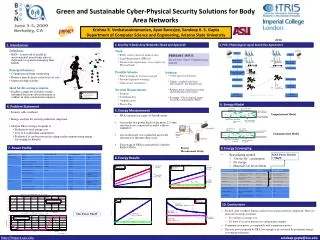
EEG Body Area Networks (BANs) EKG BP SpO2 Base Station Wearable Sensor Nodes Base Station Thermal Map of Human Body Heating effects (Unintended interactions) • Issues: • Thermal safety – keeping human body temperature within safe limits • Sustainability – un-interrupted operation with energy scavenging Motion Sensor Communication Range Aggregate Effects Communication Range (Intended Interactions) Body Sensor Network (BSN)
Model Based Communication in BAN • Use generative models for data • A light version in the sensor • A full version in the base station • Low communication overhead • Low storage requirements • Ensure required accuracy for clinically relevant data
Data Centers Heat Recirculation (Aggregate Effect) • Computing Units – • Server racks arranged in rows • CRAC unit supplies cold air from underneath the floor • Cold Ailse near server inlets • Hot aisle at the outlets Data Center Hot Air coming out of chassis (Unintended Interaction) • Issues: • Thermal Safety – schedule tasks into servers so that their inlet temperatures do not exceed manufacture specified redline temperature • Sustainability – Energy efficiency, Heat activated cooling Racks Cold Aisle CRAC Cool Air coming from CRAC (Intended Interaction) Hot Aisle Raised Floor • Interactions – • Intended – CRAC cold air cooling off racks • Unintended – re-circulated heat causing hot spots Ayan Banerjee, Tridib Mukherjee, Georgios Varsamopoulos, and Sandeep K. S. Gupta Integrating Cooling Awareness with Thermal Aware Workload Placement for HPC Data Centers , Elsevier Comnets Special Issue in Sustainable Computing (SUSCOM) 2011 (Accepted for publication).
Cyber-Physical Systems • A cyber-physical system is a system which has a computing units embedded in a physical environment • The computing unit is constantly interacting with its environment in two ways – • Intentionally – for execution of system operations • Unintentionally – through side effects of its operation • Interactions may have aggregate effects during networked operation of the CPS Computing node Space in physical environment interacted by single node Aggregate impact in space because of interactions from multiple nodes Cyber-physical interactions Cyber-Physical System (CPS)
System Requirements • Safety – Safety of any system is defined as ensuring the impact of the interactions is within desirable limits. • E.g. - keeping the temperature of the servers within redline • Sustainability - Sustainability is defined as the ability of the CPS to operate by scavenging energy from the environment. • In a BSN the sensor nodes operate by scavenging energy from human body
CPS Modeling Perspective • Network of Local CPSs • Effect of interactions are limited spatially • Intended Interactions – ROIn • Unintended Interaction – ROIm • Network of computing units imply a network of Local CPSs • Each Local CPS can affect the ROIm or ROIn of other Local CPSs • leads to complex aggregate effects of interactions A. Banerjee, S. Kandula, T. Mukherjee, and S.K.S. Gupta BAND-AiDe: A Tool for Cyber-Physical Oriented Analysis and Design of Body Area Networks and Devices , ACM Transactions in Embedded Computing Systems, Special Issue on Wireless Health 2010, Accepted for publication
Example Scenario BSN Thermal Safety Computing Unit – Atom based Sensor node running health monitoring workload Physical Unit – Human body Interaction – Heat dissipation due to computation causes temperature rise at different parts of the human body. The thermal effect of a sensor is governed by Penne’s bioheat equation Sensors close to each other have aggregate effect on the skin temperature – the heat accumulated gets summed up Heat by metabolism Heat by power dissipation Heat accumulated Heat transfer by convection Heat transfer by conduction Heat by radiation
Mapping to CPS modeling perspective Human Body Thermal Effects Sensors GCPS LCPS2 LCPS1 Aggregate effects Computing Unit Physical Unit Governed by Penne’s Equation ROIm
AADL Implementation • Industry standard Advanced Architecture Description Language • Pros - • Used in the embedded industry and can model complex systems such as aircrafts • Specific constructs for modeling the embedded computing devices • Hierarchical model specification – matches with the CPS view • Cons – • No support for modeling the physical system • Cannot represent dynamic variations of physical properties in terms of differential equations in AADL
BAN Model in AADL system BAN . . . end BAN; processimplementation application subcomponents algorithm: thread algorithm.imp1; end application; systemimplementation BAN.ins1 subcomponents Sensor1: system CompUnit.Sensor1; EnergySource: system EnergySource.impl; Body system PhysicalUnit.skin; . . . connections connection between subcomponents end BAN.ins1; threadimplementation algorithm.imp1 modes . . . properties . . . end algorithm.imp1; system implementation EnergySource.impl . . . end EnergySource.impl; system CompUnit features port specification for connections properties Computing Properties Physical Properties end CompUnit; system PhysicalUnit features port specification for information transfer properties Physical properties end PhysicalUnit; system implementation CompUnit.Sensori subcomponents P1: process application; C1: system subcomponents; connections inter-connections between the subcomponents end CompUnit.Sensori; system implementation PhysicalUnit.Skin Specify physical dynamics with the help of annexes end PhysicalUnit.Skin;
Modeling in AADL – Computing Units system Computing subcomponents P1: process SignalProcApp.impl; C1: system Radio.impl; end Computing; • Computing Units – Embedded System Constructs • system – sensors nodes in BAN • subcomponents – sensor components (e.g. radio, processor, display device etc.) • threads – application specific processes (e.g. FFT computation for signal processing applications • property sets • computing properties (e.g. operating frequency of processor) • physical properties (e.g. power dissipation of subcomponents or threads) system implementation Radio.impl properties ComputingProperty::current => 18 mA; end Radio.impl processimplementation SignalProcApp.impl subcomponents FFT: thread FFT_algorithm.imp1; end SignalProcApp.impl; threadimplementation FFT_algorithm.imp1 modes RadioOn: initialmode ; RadioOff: mode ; properties ComputingProperty::current => 19.56 mA inmodes (RadioOn); ComputingProperty::current => 1.0 mA inmodes (RadioOff); end FFT_algorithm.imp1;
Networks of computing units dataimplementation Comp2CompData.impl subcomponents SignalStrength: data behavior::float; ParentID: data behavior::integer; end Comp2CompData; • system - used for defining the network • subcomponent – used for modeling the individual computing units (sensor nodes) • port group – used for modeling connections between computing units portgroup Comp2CompPG features Packet: inoutdataport Comp2CompData.impl; end Comp2CompPG; system CompUnit features C2C: port group Comp2CompPG; end CompUnit; systemimplementation CompUnit.Sensori . . . end CompUnit.Sensori; Use of arrays required, not supported in AADL 1.0 systemimplementation BAN.ins1 subcomponents Sensor1: system CompUnit.Sensor1; Sensor2: system CompUnit.Sensor2; connections portgroup Sensor1.C2C -> Sensor2.C2CR; . . . end BAN.ins1; Replicate code for each sensor – scalable ??
Model to analyze Sustainability system implementation computing.sensor1 properties ComputingProperty::Voltage=> 2.3V end computing.sensor1; processimplementation SignalProcApp subcomponents FFT: thread FFT_algorithm.imp1; end SignalProcApp; thread FFT_algorithm properties ComputeProperty::Compute_Execution_Time => 2138 ms .. 2140 ms; ComputeProperty ::Frequency => 30 Hz; end FFT_algorithm; threadimplementation FFT_algorithm.imp1 modes RadioOn: initialmode ; RadioOff: mode ; properties ComputeProperty ::current => 19.56 mA inmodes (RadioOn); ComputeProperty ::current => 1.0 mA inmodes (RadioOff); end FFTComputation_algorithm.imp1; system BodyHeatSource properties ComputeProperty ::AveragePower=> 0.26W; end BodyHeatSource; • Power consumption of the sensor nodes were modeled • Scavenging sources were modeled for available power • Duty cycling was performed on the sensor nodes to sustain their operation using the available power • The sensor radio was turned off at appropriate times
Model to analyze side effects Behavior annex properties must be constant requiring separate property set definition for each annex Real Value initialization not supported in behavior annex • Model the physical processes • Specify differential equations • Extended Behavior Annex • Dedicated variables for parsing the differential operators • Developed a parser to recognize the operators • Developed a plug-in to convert the parsed form into solvable form • Used FDTD solver to solve the equations system implementation BAN is subcomponents Sensor: system CompUnit.impl; Body: system PhysicalUnit.impl connections port group Sensor.C2P Body.P2C; end BAN; system CompUnit features C2P: port group CyberPhysical; properties Physical Property - PowerDissipation end CompUnit; dataimplementation Comp2PhysData.impl subcomponents PowerDissipation: data behavior::float; end Comp2CompData system implementation CompUnit.impl end CompUnit.impl; portgroup CyberPhysical features Info: inoutdataport Comp2PhysData.impl; end Comp2CompPG; propertyset Coefficient is SpecificHeat: constantaadlinteger =>3600; Fixed_blood_Temp :constantaadlinteger => 37; . . . end Coefficient; system PhysicalUnit features P2C: port group CyberPhysical; end PhysicalUnit systemimplementation PhysicalUnit.impl subcomponents Del1Tt: data behavior::integer; Del2Tx: data behavior::integer; annexbehavior_specification {** states s0 : initialcompletestate; transitions s0 -[ ]-> s0 { Del1Tt := (value(Coefficient ::SpecificHeat) * Del2Tx + value(Coefficient ::blood_perfusion_constant) * (Coefficient.T - value(Coefficient ::Fixed_blood_Temp) + PowerDissipation);}; **}; end PhysicalUnit.impl; CPS specification using the behavior annex to represent differential equations Multiple data subcomponents in port groups cannot be accessed in the behavior annex
Formal Modeling • State space representation of the problem • Declare appropriate states as UNSAFE • Perform reachability analysis on the model Theoretical Guarantee on Safety and Sustainabiltiy Reduces Uncertainty of Simulation • Issues: • Current modeling techniques support dynamic variation in only one dimension • Spatio-Temporal variation of interaction effects (ROIn and ROIm) require modeling and analysis in multiple dimensions (one time and three space). • Scalability of the analysis technique on multiple dimensions • Algorithm error increases with large number of variables • Present day tools do not handle large number of variables.
System • We study systems which can be represented using a finite number of states (finite state systems). • Definition • A set of states • Set of initial states • A set of inputs • A transition relation • A set of outputs • An output map
Finite State Automata • If H maps each state in X to an yes no answer • The subset of inputs U for which the automata outputs yes is called the language • Examples: DFA, PDA, Turing Machine
Dynamical System • A dynamical system is a pair • set of continuous variables • is a set of differential equations • Often the real space is divided into equivalence classes Q • mapping of real space to equivalent classes • Concept of operating modes
Example • CRAC control system • The outlet temperature is the variable belonging to the set V • It follows the heat flow equation which is a member of the function set f • Equivalence classes can be defined on the real space to denote different operating regions of the CRAC • The COP varies in different operating regions
Hybrid Dynamical System • S is a finite state system • In is a set of invariants for each state • Invariants are conditions on the continuous variables • Gu is the set of guard conditions for each edge • Re is a reset function • If a state x is reached then what values will the continuous variables assume ? • {In,f} is a dynamical system.
Timed Automata • Hybrid dynamical system • In consists of only operators • Gu can also consist of • Re can either retain the value of the variable or set it to 0 • f can either be 0 or 1.
Formal Model for CPS • Requirements: • R1: The states in the formal model should represent both continuous and discrete domain operation • R2: The state variables can have continuous dynamics with respect to both time and space, represented by complex partial differential equations • R3: State transitions can take place through events occurring in both time and space continuum • R4: Composition of individual formal models to derive models of the system should reflect the aggregate behavior Hence a variation of hybrid automata which models spatio-temporal
Spatio-Temporal Hybrid Automata S1 S2 • Discrete Time Computational States • Discrete Physical States Discrete States S1 S2 • Continuous variables related to physical phenomenon Continuous Variables Initial State • To simulate the operation of the system in time and space S1 S2 State Transitions Guard Conditions Spatio-Temporal Threshold Equations
Formal Modeling for Safety – single sensor Single sensor node and its associated thermal effect • Notion of state is in space and time – • I1 is the state representing space in ROIm • N1 is the state representing space not in ROIm • UNSAFE state • Eq1 and Eq2 are the partial differential equations representing temperature rise in human body • State transitions occur due to events generated in space and time – • As we move through space if T1 < Tth a transition occurs from state I1 to N1 • In time also if T1 < Tth a transition occurs from state I1 to N1 • In any time at any particular state if T1 > Tsafe we go to unsafe state
Single sensor thermal profile • Thermal profile over time and space for a single sensor
Composition of models • Given individual models how to determine the model of the system Cartesian Product State Space Set of Continuous Variables Union Union including new functions to specify aggregate effects S1 S2 S11 S21 Set of Functions S12 S22 Union S1 S2 Transitions Retain old ones. If two models change state simultaneously then combine guard conditions using and operation Guard Conditions
Thermal Safety Example – model composition Unsafe T1 > Tsafe T2 > Tsafe Multiple sensor nodes and their aggregate thermal effect T2 > Tth Agg > Tsafe T1 > Tth I1 I2 I1N2 N1I2 • States are Cartesian products • Eq3 represents aggregate effect (summation of heat) • Transition from I1 ,I2 to state N1 ,N2 occurs due to a combination of events Eq1,Eq2 Eq3 = f(Eq1 , Eq2 ) Eq1,Eq2 T2 < Tth T1 < Tth T2 > Tth ∩ T1 > Tth T2 > Tth T2 < Tth ∩ T1 < Tth T1 > Tth T2 < Tth N1 N2 T1 < Tth Eq1,Eq2
STHA Analysis • Requirements • System dynamics in both space and time has to be analyzed • Solving multi dimensional partial differential equations are required • Intersection of ROIm or ROIn has to be computed • Aggregate effects in the intersecting regions have to be computed • Issues • Tools performing reachability analysis can handle dynamics in only one dimension • Multidimensional analysis requires discretization in all but one dimension • This discretization introduces error in the analysis • Drastically increases the number of dynamic variables • Current tools cannot handle large number of variables
U U U U U U U – denotes unsafe/unsustainable state STHA Analysis Procedure Reachability Analysis in successive time and space steps S State not yet reached S3 S1 S1 S1 S1 S1 S1 S3 S3 S3 S3 S3 S2 S2 S2 S2 S2 S2 S States that are reached Usafe state Reachable Halt Computation CPS STHA modified to represent dynamics in y axis CPS STHA x=nΔx x=(n-1)Δx Space discretization along x axis Hybrid System Reachability/Safety Analysis in continuous space (along y axis) x=3Δx x=2Δx x=Δx x=0 Control Space t = 0 t = Δt t = 2Δt t = 3Δt t = 4Δt Discretized Time
Conclusion and Future Work Conclusions: • Spatio-Temporal Hybrid Automata for modeling CPS • Model composition rules to take into account the aggregate effect of cyber-physical interactions • Analysis algorithm for evaluating safety and sustainability of CPS • Application of the modeling and analysis technique to three diverse case studies • Implementation of the modeling and analysis technique using industry standard AADL Future Work: • Apply STHA for medical device control systems • An accurate reachability analysis for STHA • Develop a STHA modeling and analysis tool
References • Frehse, G. 2005. Phaver: Algorithmic verification of hybrid systems past hytech. In HSCC. 258-273. • Bartocci et al, E. 2008a. Spatial Networks of Hybrid I/O Automata for Modeling Excitable Tissue. Electronic Notes in Theoretical Computer Science (ENTCS) 194, 3, 51-67. • Chow, T. 1978. Testing software design modeled by finite-state machines. Software Engineering, IEEE Transactions on SE-4, 3 (May), 178-187. • Henzinger, T. 1996. The theory of hybrid automata. Logic in Computer Science, Symposium on 0, 278. • Moser et al, L. E. 1990. Formal verification of safety-critical systems. Softw. Pract. Exper. 20, 9, 799-811. • www.aadl.info
Definition STHA The model M, called the interaction model of individual computing unit in a CPS is a tuple M = {Q,X, F, Init,E,G} where: • is a set of n + 1 discrete states. • is a set of m continuous variables associated with the model. These variables are functions of time and space. • denotes a set of spatio temporal partial differential equations for each state in Q which governs the variation of elements in X • is a set of initial states. • is a set of discrete transition relations between different discrete states in the model • is a set of conditions on the continuous variables associated with each edge in the model
Composite Model Definition Composition of models and will result in the model following a model composition relation R. The relation R consists of the following clauses • Clause 1: The set of discrete states Qc in the composite model Mc, is the Cartesian product of the two sets Q1 and Q2. However there is only one blocking state • Clause 2: The set of continuous variables Xc is the union of the two sets X1 and X2. • Clause 3: The set of functions specifies a method to combine the functions in the individual models to determine the cumulative effects of cyber-physical interactions.
Composite Model Definition • Clause 4: set of initial states • Clause 5: set of edges in Mc • Clause 6: Gc specifies the conditions for state transition. Gc is a union of four sets
CPS Annex extension • Specification of partial differential equation not supported in AADL • CPSAnnex was developed to extend AADL with the facility to specify multi-dimensional partial and total differential equations New Constructs Del, Pdel for representing total and partial derivatives Grammar