Download
1 / 35
350 likes | 357 Views
RF Links Overview. PTP and PMP Links. Full Duplex Communications. Channel 2. TX. RX. Station 1. Station 2. Channel 1. RX. TX. Two stations can talk and listen to each other at the same time. This requires two separate media.

E N D
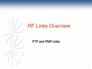
RF Links Overview PTP and PMP Links
Full Duplex Communications Channel 2 TX RX Station 1 Station 2 Channel 1 RX TX • Two stations can talk and listen to each other at the same time. • This requires two separate media. • In the case of a wireless link, 2 separate channels are required. This is referred to as Frequency Division Duplex (FDD)
Half Duplex Communications TX TX Station 1 Station 2 Channel 1 RX RX • Two stations have to take turns talking and listening. Simultaneous communications is not possible. Requires handshaking. • Two stations share a common media • This is referred to as time division duplex (TDD)
Advantages of FDD • More efficient data transfer due to lower overhead (required for handshaking). • More efficient use of spectrum in high traffic systems • Most ITU frequency bands are structured for FDD. • Half the data rate for equivalent data transfer as TDD. • Does not have latency issues associated with handshaking.
Advantages of TDD • Easier to coordinate channels than FDD. • RF Hardware is potentially less complicated and thus lower cost. • Installation may be simpler. • Only one antenna per T/R • In low traffic networks the spectrum is utilized more efficiently.
Point to Point (PTP) Links • A point to point link is one station communicating with another station, 1 to 1. • Both stations are usually similar in data-rate, modulation and overhead format. • FDD PTP links do not require media access control which reduces overhead.
Point to Point (PTP) Links • FDD PTP links do not require handshaking, this minimizes latency. • PTP links are usually used in constant bit rate applications, such as synchronous data transport and trunking applications. • PTP links can be built with extra margin to deal with fades and other impairments.
System Power Levels • Point to point link has extra system gain to increase availability. • Low probability of interference to or from other stations. • P to P links typically have narrow beam antennas.
System Power Levels PTP Links Antenna Gain 30 dB Antenna Gain 30 dB Path loss = -116 dB Station 1 Station 2 TX = +18 dBm RX = -42 dBm RX Threshold = -72 dBm
Point to Multipoint (PMP) Links PRIZM 2400 • One base station communicating with more than one subscriber on shared media.
Point to Multipoint (PMP) Links • Downstream path is from the hub to the sub. • Upstream path is from the sub to the hub. • Can use either FDD or TDD • With many subscribers PMP is more economical than PTP in both hardware and spectrum utilization.
Point to Multipoint (PMP) Links • Data-rates and modulation tend to be asymmetrical to reflect the the asymmetric flow of data in this type of system. • Media Access Control (MAC) is mandatory for a PMP system. • Typically IP based, does not work well for constant bit rate applications.
System Power Levels PMP Links • In a point to multi-point system power levels must be controlled to prevent self interference. • The Hub TX has a fixed output power. • The Hub RX has a fixed gain. • The Sub TX has a variable output power that is controlled by the RSL at the Hub RX. • The Sub RX will adjust its gain for proper RSL.
System Power Level PMP Links TX Pwr = +6 dBm RSL = -60 dBm Ant. Gain = 20 dBi Path loss =-118 dB Sub 1 Path loss =-124 dB TX Pwr = +12 dBm RSL = -66 dBm Ant. Gain = 20 dBi Sub 2 HUB Path loss =-130 dB Sub 3 TX Pwr = +18 dBm RSL = -72 dBm Ant. Gain = 20 dBi TX Pwr = +18 dBm RSL = -72 dBm Ant. Gain = 20 dBi
System Power Levels PMP Links • If an unlimited number of channels are available then self interference is not a consideration. • Within a sector subscribers will not interfere with each other due to TDMA. • Between Sectors of the same channel interference can occur, TDMA control no longer applies. • Co-channel interference occurs due to antenna side lobes, back lobes, improperly aimed antennas and reflections.
System Power Levels PMP Links • To minimize self interference... • Use minimum necessary hub TX power to reach farthest out subscriber. • Keep farthest out subscribers in center of beam if possible. • Carefully adjust elevation angle to give good signal to farthest out subscribers while still providing useable signal to close in Subs. • Make sure Sub antennas are pointed correctly, use elevation brackets if necessary. • Use maximum number of channels that is practical. • All links should be LOS, avoid reflections and obstructions.
Media Access Control • The MAC is implemented by the hub modem and controls access of the subscriber modems to the shared channel. Spike uses the DOCSIS (IEEE 802.14) MAC. • Each Subscriber is assigned one or more exclusive time slots in which they may transmit data. This is referred to as time domain multiple access (TDMA). • The Hub modem adjusts the power level of the Sub TX. • The Hub modem synchronizes all subs with the Hub and equalizes path delay.
Media Access Control • The MAC provides a means for new subscribers to join the network. • The MAC also provides for equitable sharing of bandwidth and arbitrating contention among subscribers. • The MAC must assure that all similarly provisioned subscribers have similar quality of service regardless of their location.
Broadband Wireless Example • Transceiver • Modulation Techniques • Path Analysis • Amplifier Parameters • Filter Types • Filter Technologies • PLL and Attenuators
Transceiver Design Outline • Overview • Functionality • Versions • Design Features • Basic RF Concepts
Key RF Parameters for Wireless Systems • Antenna • Gain • Sidelobe Level • Transceiver • Frequency Accuracy • Spurious Response (Regulatory Agency) • RMS Phase Error • Output Power • Modem • Data rates • Required Signal to Noise • Spurious Response (Regulatory Agency)
Modulation Techniques (0) (1) BPSK (00) (01) (10) (11) QPSK (0000) (0001) (0010) (0011) (0100) (0101) (0110) (0111) (1000) (1001) (1010) (1011) (1100) (1101) (1110) (1111) 16QAM
Modulation With Noise BPSK QPSK 16QAM
LD1 Transceiver Block Diagram Gain BPF Ceramic BPF Ceramic BPF Helical Gain Analog Atten LNA Digital Atten Loop PLL#1 Loop Receive Res. Coup. RSSI IF MCU & Control 10 MHz Reference Oscillator DUPLEXER Loop PLL#2 Loop Transmit Digital Atten BPF Ceramic PA BPF Ceramic Analog Atten Gain BPF SAWS External Reference
Amplifiers - Critical Parameters • Gain / Stability • Linearity / Output 3rd Order Intercept Point ( OIP3 ) • Output Power / 1dB Compression Point • Noise Figure
Actual Amplifier Performance F1 F2 2515.0 2515.1 F1-D 2514.9 F2-F1 0.1 F1+D 2515.2 F2+F1 5030.2 Frequency (MHz)
Mixers • Mixers are the key component for Frequency Conversion • Can be used for either Up or Down Conversion • The output response is actually: N LO + M RF Radio Frequency ( RF ) ( IF ) Intermediate Frequency = LO + RF X RF IN IF IN 35.75 MHz 420 MHz ( 360 MHz ) LO IN 384.25 MHz Local Oscillator
Filter Types Band Pass Low Pass High Pass Band Stop Diplexer fo Amplitude Frequency
Filter Technologies Type Advantages Disadvantages - Lumped Element Small size, Low cost Low Freq Limit - Microstrip/Stripline Planar, High Repeatability Large in Size - Ceramic Small size, Low Cost Low Freq Limit - Cavity High Q High Cost, Large - SAW High Rejection "in Close" High Loss ( Surface Acoustic Wave )
Transceiver Block Diagram Gain BPF Ceramic BPF Ceramic BPF Helical Gain Analog Atten LNA Digital Atten Loop PLL#1 Loop Receive Res. Coup. IF RSSI PLL1a & 2a 10 MHz Reference Oscillator DUPLEXER PLL1b & 2b Loop PLL#2 Loop Transmit Digital Atten BPF Ceramic PA BPF Ceramic Analog Atten Gain BPF SAWS External Reference • Phase Locked Loops ( PLLs ) -Stabilize the VCOs to a Reference Oscillator
Basic Phase Locked Loop PLL Chip VCO Phase Comparator 10 MHz Output Vtune ~ Div by R X Loop Filter Reference Oscillator Div by 4 Prescaler Div by N V3.0 Only
System Power Control SU r = 6 mile Pr = -83 dBm Loss = -120 dB SU Base Station SU ERP=5W r = 1000 ft Pr = -53 dBm Loss = -90 dB r = 1 mile Pr = -67 dBm Loss = -104 dB • Subscriber Receive power estimated and measured at installation • Modem Power Control will compensate for approx +15 dB of signal variation • Same attenuator setting used on Transmit side • Base Station will receive power at same level from all Subscribers
Variable Attenuators • Digital Attenuators • Coarse gain selection • Step Size / 2dB • Analog Attenuators • Fine Step Size / < .1 dB • Fine gain selection and temperature compensation