Download
1 / 37
370 likes | 405 Views
Learn how to operate and utilize the CodeVisionAVR C Compiler and integrated development environment for programming and debugging AVR microcontrollers. This chapter covers configuring projects, managing source files, and understanding compiler options.

E N D
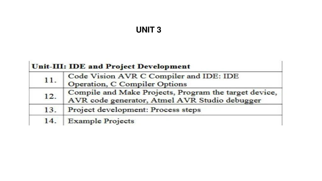
4.1 OBJECTIVES At the conclusion of this chapter, you should be able to • Operate the CodeVisionAVR C Compiler and integrated development environment • Correctly utilize the compiler options • Apply the CodeVisionAVR environment to program a target device • Apply the CodeVisionAVR code wizard to automatically generate shells of code • Apply the CodeVisionAVR terminal tool to send and receive RS-232 communications • Perform basic debugging operations using Atmel’s AVR Studio as a software simulator
The CodeVisionAVR C Compiler is just one of many C compilers available for the Atmel AVR microcontrollers. Its outstanding development environment and superb compiler determined its use in this text. Unlike a generic compiler modified for the AVR instruction set, CodeVisionAVR was written specifically for the AVR microcontrollers. As a result, it produces very precise code, using the many features of those microcontrollers without waste. In comparison with other compilers, it produces smaller, more efficient code for the Atmel AVR microcontrollers. Finally, Code- VisionAVR has the CodeWizardAVR code generator, an invaluable tool for jumpstarting most projects.
4.3.1 PROJECTS A project is a collection of files and compiler settings that you use to build a particular program.
Configure Projects The project is configured with the Project|Configuremenu command or the Project Configure toolbar button. Selecting either of these opens the Configure Project dialog box.
There are three tabbed frames in this dialog box: Files, C Compiler, and After Make. If you select the Files tab, you are able to add source files to and remove source files from the project. The C Compiler tab allows you to set properties for the project pertaining to the target device and the executable program file. Finally, the After Make tab allows you to select particular programs to run (such as a chip programmer) when the make is complete. Close Project To quit working with the current project, use the File|Close Project menu command. If the project files were modified and were not yet saved, you are prompted to save the modified files. When you save, the IDE creates a backup file with a .pr~ extension.
4.3.2 SOURCE FILES Source files are the files that contain your program source code. They are the files that you painstakingly labor over to make the microprocessor do the right thing. The IDE allows you to add source files to the project and remove them from it. The IDE also has a fairly powerful editor built into it for editing code. Open an Existing Source File To open an existing file, use the File|Openmenu command or click the Open File button on the toolbar. An Open File dialog box allows you to browse to the directory to locate the file to open. Select the file and click OK to open the file. Create a New Source File The File|New menu command and the Create New File button on the toolbar are available to create a new source file.When either is selected, a dialog box appears prompting you to select a file type. Select Source and click OK.
Add an Existing File to the Project Simply opening a file or creating a file does not automatically add it to the current project. You must open the project and select the Project|Configuremenu command or click the Project Configure toolbar button 4.4 C COMPILER OPTIONS The compiler must know some key information about the target device in order to generate the appropriate executable program file. This information includes the chip type, the data stack size of the device, and the size of the internal and external SRAM used in the application. The compiler must also know a few things about how to interpret and optimize the C code in the source files for your application.
Project|Configure menu command. The Configure Project dialog box opens, with tabbed frames for different groups of settings. Select the C Compiler tab, as shown in Figure 4–13. The two most general settings are the chip and clock. The Chip list box selects the target AVR microcontroller chip. (Note that the evaluation and lite versions of CodeVisionAVR The required memory model is selected under Memory Model. Four memory models are implemented: Tiny, Small, Medium, and Large. The Tiny option uses 8 bits for storing pointers to the variables placed in SRAM. In this memory model, you have access to only the first 256 bytes of SRAM. The Small option uses 16 bits for storing pointers to the variables placed in SRAM. In this memory model, you have access to 65,536 bytes of SRAM. For both the Tiny and Small options, the pointers to the FLASH and EEPROM memory areas always use 16 bits, so the memory model selection limits the total size of the constant arrays and literal character strings to 64K.
4.5.2 MAKE A PROJECT An executable file is created by making a project. To make a project, select the Project|Make menu command, press the Shift+F9 keys, or click the Make button of the toolbar. TheCodeVisionAVRC Compiler executes, producing an assembler source file with the .asm extension. If the compiler generated no errors, the Atmel AVR assembler AVRASM32 is automatically called, and the assembler runs on the newly created assembler source file. The assembler creates an executable program file in the format specified in the C Compiler tab of the Configure Project dialog box (Project|Configure|C Compiler command). After the make process is completed, the Information window opens, showing the compilation results. There are two tabs in the window, Compiler and Assembler
4.6 PROGRAM THE TARGET DEVICE The CodeVisionAVR IDE has a built-in In-System AVR Chip Programmer that lets you easily transfer your compiled program to the microcontroller for testing. The programmer is designed to work with development boards such as the Atmel STK500, Kanda Systems STK200+/300, Dontronics DT006, Vogel Elektronik VTEC-ISP, and the MicroTronicsATCPUand Mega2000 development boards, which are connected to your computer’s parallel printer port. The Settings|Programmer menu item opens a window to select the type of programmer to be used. The programmer is opened by selecting the Tools|Chip Programmer menu command or by clicking the Chip Programmer button on the toolbar.
4.6.4 FUSE BITS If the chip you have selected has fuse bits that can be programmed, a supplementary Fuse Bit(s) frame appears. In this frame are various check boxes, one for each fuse bit available on the selected chip. The 4.6.5 BOOT LOCK BIT 0 AND BOOT LOCK BIT 1 Chips that support boot-loading applications have additional security bits that lock the boot loader section of memory. The Boot Lock Bit 0 and Boot Lock Bit frames and options support these additional security bits 4.6.6 SIGNATURE Each different chip type in the Atmel AVR line has a unique signature. The Read|Chip Signature menu item reads the signature of the chip to determine the type of chip connected to the programmer. Many programmers use the signature to verify the chip selected against the actual hardware connected before performing any operation.
4.6.7 CHIP ERASE A chip erase is automatically performed whenever the Program|All menu command is used. To erase a chip independent of the programming operation, the menu command Program|EraseChip is available. The Program|BlankCheck menu command verifies that the chip’s EEPROM and FLASH memory areas are erased. This verification is also performed automatically by the Program|Allfunction unless the Check Erasure check box is cleared.
4.9 THE ATMEL AVR STUDIO DEBUGGER Both software simulators and in-circuit-emulators are useful for debugging software and are sometimes referred to as debuggers. Most include some method of starting, stopping, and stepping through a program. Most also allow the user to peek at and even modify registers and variable values. CodeVisionAVRis designed to work in conjunction with a particular debugger, the Atmel AVR Studio debugger version 4.06 or later. AVR Studio is a software simulator for Atmel’s AVR parts. AVR Studio also supports in-circuit emulators such as Atmel’s ICE 200, ICE 50, and JTAG ICE. AVR Studio is available free from Atmel’s Web site at http://www.atmel.com/. There are some basic operations that are useful to every programmer: loading a C file for debugging; starting, stopping, and stepping through a program; setting and clearing breakpoints; and viewing and modifying variables and machine state.
Debuggers also usually require specially formatted files. These files contain information about the format of the C file, variable names, function names, and other such information. The files used by AVR Studio are denoted with a .cofextension. CodeVisionAVR is designed to create this type of file and to launch AVR Studio from a toolbar button. 4.9.1 CREATE A COFF FILE FOR AVR STUDIO A COFF file is required to perform C source-level debugging in AVR Studio. To create this type of file in CodeVisionAVR, select the Project|Configuremenu item to open the Configure Project dialog box. Select the C Compiler tab; in the lower right corner is the File Output Format(s) list box. Select the COFF, ROM,HEX, EEP list item. Click OK to close the window and save the setting.
4.9.2 LAUNCH AVR STUDIO FROM CODEVISIONAVR C:\Program Files\Atmel\AVR Tools\AvrStudio4\AVRStudio.exe 4.9.3 OPEN A FILE FOR DEBUG AVR Studio refers to the debugger source files as Object Files.To open the .coffile created byCodeVisionAVRfor debugging, select the File|OpenObjectfilemenu item and browse to your file. Select your .coffile and click OK. This 4.9.4 START, STOP,AND STEP Before we dive into this very important debugger topic, we need to review one point about AVR Studio: It has two modes, editing and debugging.Underthe Debug menu are two items that tell which mode you are in, Start Debugging and Stop Debugging. Only one ofthese items is available at a time. If Start Debugging is available (not disabled, grayed out), select it to enter debugging mode. If Start Debugging is disabled, then you are already in debugging mode.
4.9.5 SET AND CLEAR BREAKPOINTS A very useful tool in most debuggers is the ability to set and clear breakpoints. These are points in your program where you want execution to halt. Once it is halted, you can review variable or register values, or you can choose to start single-stepping the program to determine exactly what it is doing. Once the breakpoints are set, run your program as usual. The program halts before executing the selected line. After the program is halted, all of the information in all of the windows is updated. 4.9.6 VIEW AND MODIFY REGISTERS AND VARIABLES In the View menu are listed the items Watch, Memory Window, and Register. These menu items bring up windows to display variables, various parts of memory, and registers, respectively. The information in these windows is not updated while the program is running. Once program execution is halted, by either a breakpoint or the user commanding a break, the information in all of the windows is updated. .To change the value of the variable, double-click the Value column and type in the new value. The Memory window overlays the other active windows and allows you to view various memory spaces, including EEPROM, Data, I/O, Program, and Register. Here, you can directly watch memory being modified. Double-clicking a value allows you to enter a new value, and the Address box at the top allows you to specify the address of the space you want to view.
Registers 0 through 31 can be viewed in many ways. To simply see them all displayed at once, select the View|Registersmenu item. Double-clicking a particular register allows you to modify its value. . 4.9.7 VIEW AND MODIFY THE MACHINE STATE Sometimes it is very useful to look at the exact state of the microprocessor. What are the counters doing? Where is the stack pointer? What is going on with the I/O? Along the left side of the AVR Studio screen is a Workspace frame. Along the bottom of this frame are three tabs: Project, I/O, and Info. The I/O tab gives us the capability of looking at the machine state and modifying it.
Project Development 5.3 CONCEPT DEVELOPMENT PHASE Every project is based on an idea or concept, which comes from any need—somebody “wants one.” The need may be to fill a gap in a product market, to improve a production process, to meet a course requirement, or simply to create something that has not been created before. Because projects are often started to satisfy a need, the original description of the project is sometimes called a problem statement or a need statement. 5.4 PROJECT DEVELOPMENT PROCESS STEPS The steps you should follow in the process of developing a project are as follows: 1. Definition phase 2. Design phase 3. Test definition phase 4. Build and test the prototype hardware phase
5.4 PROJECT DEVELOPMENT PROCESS STEPS The steps you should follow in the process of developing a project are as follows: 1. Definition phase 2. Design phase 3. Test definition phase 4. Build and test the prototype hardware phase 5. System integration and software development phase 6. System test phase 7. Celebration phase
5.4.1 DEFINITION PHASE Defining the project has the objective of clearly stating what the project is to accomplish. This step involves specifying what the device is to do, researching to ascertain that the project is, in fact, feasible, developing a list of specifications that fully describe the function of the project, and, in a commercial environment, providing a formal proposal to go ahead with the project. This step is sometimes called the feasibility study. At the end of the definition phase, a complete set of specifications for the project is developed. These include electrical specifications as well operating specifications that detail the operation and human interface to the project.
In a commercial environment, a Project Proposal is written to summarize the definition phase of the project Project Title A. Description of project. This section will fully describe the project, its overall function, the reason or rationale to complete the project, and an indication of the benefits expected to arise from completion of the project. The purpose of this section is for the reader to understand what the project is and why it is important. B. Summary of Research. The project research completed during this phase of the project is summarized, including research done on the market and/or competing products, on similar or related projects or products, as well as the results of any proof-of-concept testing completed. The purpose of this section is to show that the project has been thoroughly researched to assure that the relationship of this project to other, existing, projects is clear. C. Block Diagram. The overall, macro-level, block diagram is presented in this section. Following the block diagram is a discussion of the function of each block as it relates to the project’s overall function. The purpose of this section is to give the reader confidence that the project can be completed successfully.
D. Project Budget. A detailed budget is presented here to show all the expected expenditures, including labor and materials, associated with this project. E. Project Schedule. The project schedule shows the milestones for starting and completing each block, for starting and completing each phase of the development process, for review or reporting points in the project, and for the final completion and presentation of the project. The purpose of this section is toc show, realistically, the time it will take to complete the project and to givec the reader confidence that the project has been thoroughly planned out. F. Appendix. The appendix includes the bibliography developed during research and any other information that is too large to be included in the text.
The definition phase is a relatively short but very critical step that consumes approximately 10 to 15 percent of the total project time
5.4.2 DESIGN PHASE The major goal of the design phase of the project is to fill in the macro blocks developed during the definition phase with actual circuitry and to plan out, in flowchart form, the project software. Because the hardware and software of the project are intimately related, the hardware design and the software plan must be accomplished concurrently. When thoroughlydone, this step will consume 40 to 50 percent of the total project time. • Designing the project is the step that, more than any other step, determines the success of the project, both in terms of function and efficient development—for efficient, read “on time and under budget.” • Designing the project is the step that is most neglected, disliked, and even hated by engineers, who vastly prefer hooking up hardware or writing programs to doing research and paperwork.
Software development steps: List the tasks to be completed by the software. 2. Prioritize the tasks and determine which are critical and will need to be handled on an interrupt basis and which are less critical. Using our example, timing the speed pulses would probably be considered critical and, hence, a candidate for an interrupt, whereas updating the display would probably be considered a low-priority task that could be completed whenever the processor is not doing more critical tasks. 3. Create a software flowchart or outline for each interrupt function. 4. Create a software flowchart or outline of the program code to complete the project’s entire task.