Download
1 / 17
190 likes | 490 Views
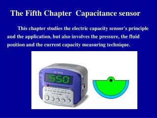
Chapter 25: Capacitance and Dielectrics. Capacitor: two conductors (separated by an insulator) usually oppositely charged. a +Q. b -Q. V ab proportional to charge Q C = Q/ V ab (defines capacitance) units: 1F = 1 C/V. The parallel plate capacitor. A. +Q. d. A. -Q.

E N D
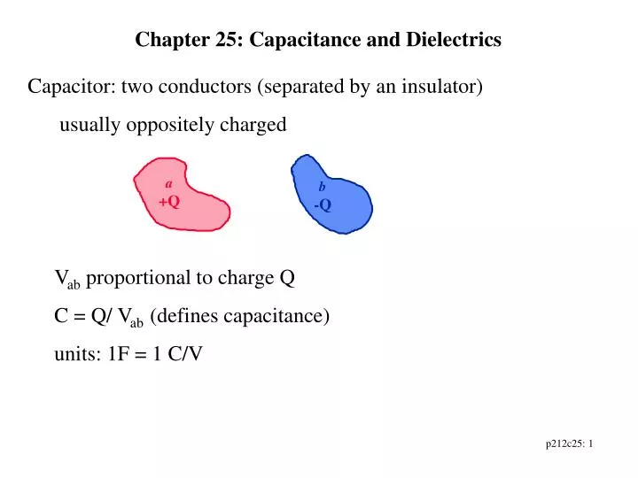
Chapter 25: Capacitance and Dielectrics • Capacitor: two conductors (separated by an insulator) • usually oppositely charged a +Q b -Q • Vab proportional to charge Q • C = Q/ Vab (defines capacitance) • units: 1F = 1 C/V
The parallel plate capacitor A +Q d A -Q • Capacitance does not depend upon Q, V! • => C depends upon geometric factors only • How big is 1 Farad? (parallel plate example)
Typical Capacitances ~ mF, nF, pF • Example: A parallel plate capacitor has plates 2.00 m2 in area, separated by a distance of 5.00 mm. A potential difference of 10,000 V is applied across the capacitor. Determine • the capacitance • the charge on each plate • the magnitude of the electric field in the region between the plates.
A long cylindrical capacitor L ra rb
A long cylindrical capacitor, small distance between cylinder walls L ra rb Capacitor looks approximately like parallel plates, in appropriate limit.
Capacitors in circuits • symbols • analysis follow from • conservation of energy (in terms of electric potential) • conservation of charge
a +Q1 C1 -Q1 V=Vab c +Q2 C2 -Q2 b Capacitors in series A 3 mF capacitor and a 6 mF capacitor are connected in series across an 18 V battery. Determine the equivalent capacitance, the charge on each capacitor and the potential difference across each capacitor.
a C1 +Q1 C2 +Q2 V=Vab -Q1 -Q2 b Capacitors in parallel A 3 mF capacitor and a 6 mF capacitor are connected in parallel across an 18 V battery. Determine the equivalent capacitance, the potential difference across each capacitor and the charge on each capacitor.
C1 C5 C3 C2 C4 Combinations of combinations can be analyzed piecewise C2 C1 C3 Some configurations are not combinations that can be treated as combinations that can be analyzed as serial/parallel
Energy stored in a capacitor • When charged: Q = CV • Charging q = Cv dq dq q v = q/C q -q -q -dq dq
+ + + + + + + + + + + - - - - - - - - - - - • Electric Field Energy • Uniform field: parallel plate capacitor
C1 V C2 C3 • In the circuit shown V = 48V, C1 = 9mF, C2 = 4mF and C3 = 8mF. • (a)Determine the equivalent capacitance of the circuit, • (b) determine the energy stored in the combination by calculating the energy stored in the equivalent capacitance, • (c) calculate the charge on and potential difference across each capacitor and • (d) calculate the energy stored in each individual physical capacitor.
-Q -Q +Q +Q • Dielectrics: insulating materials with other interesting properties • In parallel plate capacitors • For a charged, isolated capacitor V0 V • potential difference decreases • same charge => capacitance increases • C = Q/V > C0 = Q/V0 • Dielectric Constant: K = C/C0 • material property
Effect of dielectric on Electric field • parallel plates, constant charge • Q = CV = C0V0 => V = V0/V (reduced) • => E = E0/K • Material is polarized • Effective surface charge distribution +s -s -si +si +snet =s-si -snet =-(s-si)
Example 25-8: • Take a parallel plate capacitor whose plates have an area of 2000 cm2 and are separated by a distance of 1cm. The capacitor is charged to an initial voltage of 3 kV and then disconnected from the charging source. An insulating material is placed between the plates, completely filling the space, resulting in a decrease in the capacitors voltage to 1kV. Determine the original and new capacitance, the charge on the capacitor, the dielectric constant of the material, the permittivity of the dielectric, the original and new electric fields, the energy stored in the capacitor with and without the dielectric.
- + + - + - - - - - - + + + + + - - + + - + - - - - - + + + + + - + + - + - - - - - - + + + + + - - + - + - - - - - + + + + + + + + + + - - - - + + + + - - - - + + + + - - - - + + + + - - - - How does an insulating dielectric material reduce electric fields by producing effective surface charge densities? Reorientation of polar molecules Induced polarization of non-polar molecules Dielectric Breakdown: breaking of molecular bonds/ionization of molecules.
Polarization (approximately) proportional to applied Electric Field • beyond linear approximation: nonlinear optics... • Dielectric materials and Gauss’s Law