Download
1 / 12
120 likes | 258 Views
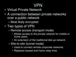
An Architecture of Instant VPN draft-li-l3vpn-instant-vpn-arch-00. Zhenbin Li, Yuanbin Yin ( Huawei Technologies) IETF 88, Vancouver ,BC, Canada. Why need Instant VPN. Cloud DC. Cloud DC. Enterprise site. Provider Network. Enterprise site. Enterprise Site. Enterprise Site.

E N D
An Architecture of Instant VPN draft-li-l3vpn-instant-vpn-arch-00 Zhenbin Li, Yuanbin Yin (Huawei Technologies) IETF 88, Vancouver,BC, Canada
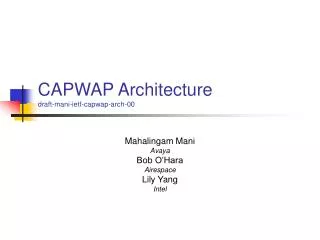
Why need Instant VPN Cloud DC Cloud DC Enterprise site Provider Network Enterprise site Enterprise Site Enterprise Site Enterprise Site With the wide application of cloud computing technology, more and more enterprises will hire public cloud data center resources, reduce their own costs. Providers need to enterprise data center rental network and enterprise own network connected together, provide enterprise lease line services. L3VPN is most providers provide this service selection. New VPN line business needs to rapidly deploy, but the current technology cannot meet this requirement.
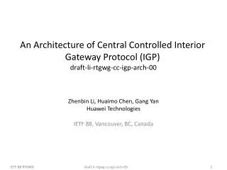
PE PE PE PE Instant VPN Architecture VPN user Information Input VPN User Interface VPN User Authentication VPN User Management VPNRoute Management VPN Controller CE 1. Enterprise user input their user information, like VPN ID, CE ID, Access strategy between CEs, Routing protocol between CE and PE, etc when they want to apply VPN service to provider. Provider Network CE 2. The VPN controller of Provider receive and manage these information. 3. The enterprise CE send authentication request to PE when CE boot, PE relay the request to VPN controller, VPN controller will verify the VPN information, generate automatically the configuration of VPN and send to PE if authentication pass. CE 4. PE receive the configuration and create the VRF instance, and setup the tunnel automatically. CE
Instant VPN Architecture VPN Controller Function VPN User Interface 1. Provides the interface for the enterprise VPN user to input VPN information which will be saved to the VPN User Management module. 2. Provide VPN information query interface to view the VPN information through the interface, such as the current on-line of CE ID, PE address which CE accessed to, VPN tunnel information, VPN SLA etc. VPN Authentication 1. Receive the authentication request message of CE from PE. 2. Being responsible for the authentication of VPN users on-line by examining the VPN ID+CE ID and CE password. 3. Reply message with VPN information for the users that pass the authentication successfully . VPN User Management 1. Being responsible for the management of all providers of VPN user information, including: VPN ID, CE ID, CE password, Access strategy between CEs, Routing protocol between CE and PE, IP address and mask connected between CE and PE, 2. Automatic generating of configuration for each access CE, including VRF name, RD, RT information. 3. Management of all on-line VPN users, including all CE IDs, PE addresses which CE accessed to, etc. VPN Route Management 1. Receives all VPN routes from all PEs. Calculate routes for each VRF based on each VRF's IRT. 2. Send the VRF routes to PE based on the strategy of center control. 3. Apply the route policy centrally to control the route distribution.
Instant VPN Architecture PE Function VPN User Management 1. Receive authentication request message from CE, including VPN ID, CE ID, CE password, and send authentication request to VPN controller. 2. Receive authentication response message from VPN controller, including authentication result, VPN ID, CE ID, the routing protocol running with CE, the CE interface IP address and mask which access to PE, the PE interface IP address and mask which access to CE, the CE AS number and PE AS number if route protocol is BGP, and send the authentication response message to CE. 3. Manage all CE users, recording VPN ID, CE ID, the CE access interface etc. VRF Instance Automatically Create 1. Create VRF instance based on the configuration which VPN controller sent, configure the RD and RT automatically. 2. Bind the CE access interface with VRF automatically. Access Side Configure Automatically 1. Configure the IP address and subnet mask of the interface which access to CE based on the authentication response message. 2. Configure the route protocol based on the message which VPN controller sent. VPN Tunnel Automatically Setup 1. For each VRF, receive the following information which VPN controller sent: ---The PE IP address list which can access to the VPN. ---The tunnel information including tunnel type, tunnel bandwidth and other constraints if MPLS TE tunnel is used. 2. Set up the tunnel automatically with each PE.
Instant VPN Architecture CE Function 1. Automatically initiate VPN user authentication request to PE. 2. Receive VPN user authentication response message including the CE IP address and mask, the route protocol between CE and PE, the PE IP address and AS number if protocol is BGP. 3. Configure the interface IP address, mask and route protocol automatically.
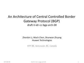
PE PE PE PE Instant VPN Procedures-VPN User Authentication Process VPN user Information Input • Authentication • request/response VPN User Interface • Authentication • request/response VPN User Authentication VPN User Management VPNRoute Management VPN Controller VPN User Authentication Process Step 1: CE initiates VPN service request to PE automatically , carrying the VPN ID, CE ID, CE password. Step 2: PE receives the authentication request and sends the authentication request to VPN Controller. Step 3: VPN Controller receives and processes the authentication request through the VPN Authentication module based on the information input by the enterprise users. Step 4: If the authentication passes, VPN Controller sends authentication success message to PE, carrying information: VPN ID, CE ID, the routing protocol between CE and PE, the CE IP address and mask, the PE IP address and mask, the CE AS number and PE AS number if routing protocol is BGP. Step 5: PE decapsulates authentication success message. If the routing protocol between CE and PE is BGP, PE's own AS number and IP address will be encapsulated in an authentication success message and sent to CE. CE Provider Network CE CE CE
PE PE PE PE Instant VPN Procedures-VRF Instance Configuration VPN user Information Input VPN User Interface • VRF configuration VPN User Authentication VPN User Management VPNRoute Management VPN Controller VRF Instance Configuration Step 1: After the CE authentication passes, VPN Authentication module informs VPN User Management module. Step 2: VPN User Management module creates an VRF instance for the CE user, automatically generating VRF RD, import RT and export RT information. Step 3: VPN User Management module sends VRF configuration information to the corresponding PE. Step 4: PE receive the VRF configuration from VPN controller, and create VRF automatically, binding VRF with the interface which CE access to. CE Provider Network CE CE CE
PE PE PE PE Instant VPN Procedures- Route Protocol Configuration Between PE and CE VPN user Information Input VPN User Interface • route configuration • Authentication • response VPN User Authentication VPN User Management VPNRoute Management VPN Controller Route Protocol Configuration Between PE and CE Step 1: After the CE user authentication passes, VPN User Management gets the routing protocol information between CE and PE and automatically generates the routing protocol configuration of the PE. If the BGP protocol runs between the CE and the PE, the CE's IP address and AS number are also required. If the enterprise define the access strategy, also generates the route policy configuration. Step 2: VPN User Management sends the configuration to PE to compete the configuration automatically. Step 3: After the CE receives the authentication success message from PE, it can get the route protocol type between CE and PE. If the protocol is BGP, it can also get the PE's IP address and AS number from the message. Then the CE can complete the routing configuration automatically. CE Provider Network CE CE CE
PE PE PE PE Instant VPN Procedures- VRF Route Distribution VPN user Information Input • VPN route VPN User Interface • Private route VPN User Authentication VPN User Management VPNRoute Management VPN Controller VRF Route Distribution Step 1: BGP peers establish automatically between the PE and the VPN Controller. Step 2: CE advertises its routes to PE. Step 3: PE advertises the routes which are received from CE to the VPN controller. VPN controller processes the routes through VPN Route Management module. Step 4: VPN Route Management module receives VRN routes of all on- line CE and calculate routes for each VRF according to the VRF RT value. Step 5: In the controller the enterprise users can configure specific policy for each CE or PE to control the route distribution, such as the removal of specific routing prefixes. Step 6: VPN Controller advertises the VRF routes to the corresponding PE. Step 7: PE receives and installs the VRF routes. Then the PE sends routes to CE. CE Provider Network CE CE CE
PE PE PE PE Instant VPN Procedures- VPN Tunnel Establishment VPN user Information Input • VPN Tunnel information • VPN Tunnel information VPN User Interface VPN User Authentication VPN User Management VPNRoute Management VPN Controller If the enterprise user does not define the bandwidth and other constraints between CEs, the tunnel for the VPN can use LDP or GRE, VXLAN and other types of tunnels. If the enterprise users define the bandwidth or other constraints between CEs, MPLS TE tunnel can be used. Based on VRF RT information of PEs, VPN controller determine the tunnels which should be set up among these PEs of the VPN. When a new CE is online, VPN Controller will send the PE lists to a specific PE. The PE lists determines the tunnels which the specific PE need to set up to these PEs. In addition, the tunnel type can also be advertised to the PE. If MPLS TE tunnel is used, the MPLS TE constraint for the tunnel can also be advertised. When the PE received the PE list, it should establish the tunnel with the other PE members specified by the PE list. CE Provider Network CE CE CE
Next Steps • Solicit comments and feedback • Revise the draft