Download
1 / 37
370 likes | 554 Views
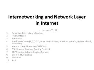
Internetworking and the Internet Protocol (IP). Network Layer Functions. Network Layer Objectives Transport (switch) packet from sending to receiving hosts Network layer protocols in every host, router Three Necessary Functions

E N D
Network Layer Functions • Network Layer Objectives • Transport (switch) packet from sending to receiving hosts • Network layer protocols in every host, router • Three Necessary Functions • Path Compuation: route taken by packets from source to dest. “Routing” algorithms • Switching: move packets from router’s input to appropriate router output • Call Setup: some network architectures require router call setup along path before data flows
t1 t0 Network Service Model Q: What service model for “channel” transporting packets from sender to receiver? • guaranteed bandwidth? • preservation of inter-packet timing (no jitter)? • loss-free delivery? • in-order delivery? • congestion feedback to sender? • Virtual Circuit vs. Datagram service Network
IP (Inter-networking) Protocol • Challenges at Network Layer for Internetworks • Service Models • Best Effort Service Model • Global Addressing Scheme • Internetworking is the effective communication among users in different networks • Heterogeneity in networking technologies; • Applications should work on different types of networks and internetworks; • Internetworks should be scalable and leverage economies of scale.
Challenge 1: Different Address Formats • Provide one common format map lower level addresses to a common format • IPv4 address format: 32 bit length, hierarchical organization 24 7 Class A Network 0 Host 14 16 Class B Network 1 0 Host 21 8 Network Class C 1 1 0 Host 28 Class D 1 1 1 0 Multicast address 27 Class E 1 1 1 1 0 Unused
Challenge 2: Different Packet Sizes • Define a maximum packet size over all networks. Why not? • Implement fragmentation/re-assembly • who is doing fragmentation? • who is doing re-assembly?
Other Challenges • Errors require end-to-end reliability • Add a transport layer on top of IP • Different (routing) protocols coordinate these protocols
Network 1 (Ethernet) H7 R3 H8 Network 2 (Ethernet) H2 H1 H3 Network 4 (point-to-point) R1 R2 H4 Network 3 (FDDI) H5 H6 H1 H8 TCP TCP R3 R2 R1 IP IP IP IP IP FDDI PPP ETH ETH ETH FDDI PPP ETH IP Internets • Concatenation of Networks • Protocol Stack
Network Layer on End-Points and Routers • Routers (“gateways”) Machine A Machine B Application Application Router/Gateway Transport Transport Internet Internet Internet Network Interface Network Interface Network Interface Network 2 Network 1
IP Related Protocols Application Application TCP UDP Network Layer ICMP IP ARP RARP Physical Network
Receiver Sender Application Application data data TCP UDP TCP UDP TCP/UDP data TCP/UDP data IP IP TCP/UDP data TCP/UDP data IP IP TCP/IP – Headers • IP header used by IP (Network Layer) for IP routing, fragmentation, error detection, etc. • UDP header used by UDP (Transport Layer) for multiplexing/demultiplexing, data error detection • TCP header used by TCP (Transport Layer) for multiplexing/demultiplexing, flow and congestion control
Transport Layer: TCP, UDP, OSFP, etc. IP protocol • addressing conventions • datagram format • packet handling conventions Routing protocols • path selection • RIP, OSPF, BGP Network Layer Routing Table ICMP protocol • error reporting • router “signaling” Link Layer physical Layer The Internet Network Layer Host / Router network layer functions:
0 4 8 16 19 31 Version TOS Length HLen Ident Flags Offset TTL Protocol Checksum SourceAddr DestinationAddr Options (variable/optional) Pad (variable) Data IPv4 Service Model • IPv4 [RFC 791] • Datagram-switching: Connectionless model. • Best-effort delivery: Unreliable service • packets can get lost • packets can be delivered out of order • duplicate copies of a packet are delivered • packets can be delayed for a long time • Datagram format • 64KB maximum size • IP Header (20B min) • Current version IPv4 • IPv6 is next generation IPAll vendors support it • IP datagram data payload
0 4 8 16 19 24 31 Version IHL Type of Service Total Length Identification Flags Fragment Offset Time to Live Protocol Header Checksum Source IP Address Destination IP Address Options Padding IP Datagram Format: IP Header Max Size = 64KB • IP Header • HLen – header length in 32-bit words (5 HLen 15) • TOS (Type of Service): Reliability, Latency, Throughput. Now split in • Differentiated Service (DS) Field (6 bits) • other two bits used by ECN (Early Congestion Notification) • Length – the length of the entire datagram/segment; header + data • Flags: Don’t Fragment (DF); More Fragments (MF) • Fragment Offset – all fragments excepting last one contain multiples of 8 bytes • Header Checksum - uses 1’s complement (IP Checksum)
IP protocol version number 32 bits total datagram length (bytes) header length (words) type of service head. len ver length fragmentation / reassembly minimum fragment size = 576 fragment offset Type of Service flgs 16-bit identifier Time-to-Leave max number remaining hops (decremented at each router) upper layer time to live Internet checksum 32 bit source IP address 32 bit destination IP address Options timestamp, record route taken, specify list of routers to visit, etc. Options (if any) Upper layer protocol to deliver payload to ICMP=1, TCP=6, UDP=17, OSPF=89, etc. data (variable length, typically a TCP or UDP segment) IP Datagram Format
IP Datagram Format: IP Header Fields • IPversion [0.0..3] – • 4 = current, 6 = next generation IP “IPng” or IPv6, 5 = ST2 (a Real-Time stream protocol) • Header Length [0.4..7] – in 32bit words • Type of Service [0.8..15] – (preferences 4b, priorities 3b): • min delay, min $cost, max throughput, max reliability; • most routers ignore ToS; OSPF can use it; • DiffServ uses it as • differentiated Service (DS) Field (6 bits) • other two bits used by ECN (Early Congestion Notification). • Total Length [0.16..31] – in bytes 216 • Id, Flags, Offset [1.0..31] – used in fragmentation • Time To Live (TTL) [2.0..7] – maximum number of hops DG can be forwarded.
IP Datagram Format: IP Header Fields • Protocol [2.8..15] – the Transport Layer user of this DG: • ICMP = 1, TCP = 6, UDP = 17, OSFP = 89, etc. • Header Checksum [2.16..31] – “IP Checksum” over the IP header fields [RFC 1071, RFC 1141] • Source IP [3.0..31] / Destination IP[4.0..31] Addresses – • IP numbers of sending and receiving hosts • Options [Variable Length] – Optional fields, requesting particular handling of current IP DG. • they complicate processing per IP DG in routers. • IPv6 allows more efficient handling of options via “extension headers”
Fragmentation and Reassembly • Each network has some MTU • Maximum Transmission Unit (MTU) maximum packet size that can be carried by a L2 link. Path MTU := mini { MTUi } • IP Strategy: • fragment when necessary (if MTU < Datagram); avoid fragmentation at source host • re-fragmentation is possible (if MTU < Fragment) • fragments are self-contained datagrams • delay reassembly until destination host • do not recover from lost fragments • ATM: use CS-PDU (not ATM cells) Source Router Destination Message IP IP MTU-2 MTU-1 Network Network
Start of header Offset=0 Ident = x 0 Rest of header 1400 data bytes Start of header Ident = x Offset=0 1 Rest of header 512 data bytes Start of header Offset=512 Ident = x 1 Rest of header H8 R2 H1 R1 R3 512 data bytes Start of header Ident = x Offset=1024 0 ETH IP (1400) FDDI IP (1400) PPP IP (512) ETH IP (512) Rest of header PPP IP (512) ETH IP (512) 376 data bytes PPP IP (376) ETH IP (376) Fragmentation and Reassembly Example • Maximum Transmission Units DLL MTU (Bytes) 802.3/802.2 1500 Ethernet 1492 FDDI 4352 802.5 (4/16) 4464/17914 X.25 576 PPP 296 Hyperchannel 65535
223.1.2.1 223.1.1.1 223.1.1.2 223.1.2.9 223.1.1.4 223.1.3.27 223.1.1.3 223.1.2.2 223.1.3.1 223.1.3.2 223.1.1.1 = 11011111 00000001 00000001 00000001 223 1 1 1 IP Addressing: Introduction • IP Address: a unique 32-bit identifier for host, router interface • Interface (i/f):connection between host / router and physical link • routers typically have multiple interfaces • host may have multiple interfaces • IP addresses associated with interface, not host or router
223.1.2.1 223.1.1.1 223.1.1.2 223.1.2.9 223.1.1.4 223.1.3.27 223.1.2.2 223.1.1.3 LAN 223.1.3.2 223.1.3.1 network consisting of 3 IP networks (for IP addresses starting with 223, first 24 bits are network address) IP Addressing • IP Address: (Network, Host) • network part (high order bits) • host part (low order bits) • What’s a network ? (from IP address perspective) • device interfaces with same network part of IP address • can physically reach each other without intervening router
0 1 2 3 8 16 31 Bit position: Net ID Host ID Class A 0 Net ID Host ID Class B 1 0 Net ID Host ID Class C 1 1 0 Multicast Address Class D 1 1 1 0 Reserved for experiments Class E 1 1 1 1 IP: Global Addresses • Properties • globally unique, meaningful to IP layer; • hierarchical: network + host • Five classes of IP addresses “Classful Addressing”
223.1.3.27 223.1.3.1 223.1.3.2 IP Addressing 223.1.1.1 How to find the networks? • Detach each interface from router, host • Create “islands” of isolated networks 223.1.1.2 223.1.1.4 223.1.1.3 223.1.7.0 223.1.9.2 223.1.7.1 223.1.9.1 223.1.8.1 223.1.8.0 Interconnected system consisting of six networks 223.1.2.6 223.1.2.1 223.1.2.2
Getting a Datagram from Source to Dest routing table in A Dest. Net. next router Nhops source IP addr misc fields dest IP addr data 223.1.1 1 223.1.2 223.1.1.4 2 223.1.3 223.1.1.4 2 223.1.1.1 A 223.1.2.1 223.1.1.2 223.1.2.9 223.1.1.4 B 223.1.2.2 E 223.1.3.27 223.1.1.3 223.1.3.2 223.1.3.1 IP Datagram: • Datagram remains unchanged, as it travels source to destination • Addr fields of interest here
misc fields Dest. Net. next router Nhops 223.1.1.1 data 223.1.1.3 223.1.1 1 223.1.2 223.1.1.4 2 Starting at A, given IP datagram addressed to B: • look up net. address of B • find B is on same net. as A • link layer will send datagram directly to B inside link-layer frame • B and A are directly connected 223.1.3 223.1.1.4 2 223.1.1.1 A 223.1.2.1 223.1.1.2 223.1.2.9 223.1.1.4 B 223.1.2.2 E 223.1.3.27 223.1.1.3 223.1.3.2 223.1.3.1 Getting a Datagram from Source to Dest
Getting a Datagram from Source to Dest misc fields 223.1.1.1 data 223.1.1.3 Dest. Net. next router Nhops 223.1.1 1 223.1.2 223.1.1.4 2 223.1.3 223.1.1.4 2 223.1.1.1 A 223.1.2.1 223.1.1.2 223.1.2.9 223.1.1.4 B 223.1.2.2 E 223.1.3.27 223.1.1.3 223.1.3.2 223.1.3.1 Starting at A, dest. E: • look up network address of E • E on different network • A, E not directly attached • routing table: next hop router to E is 223.1.1.4 • link layer sends datagram to router 223.1.1.4 inside link-layer frame • datagram arrives at 223.1.1.4 • continued…..
Getting a Datagram from Source to Dest misc fields 223.1.1.1 data 223.1.1.3 Dest. next network router Nhops interface 223.1.1 - 1 223.1.1.4 223.1.2 - 1 223.1.2.9 223.1.3 - 1 223.1.3.27 223.1.1.1 A 223.1.2.1 223.1.1.2 223.1.2.9 223.1.1.4 B 223.1.2.2 E 223.1.3.27 223.1.1.3 223.1.3.2 223.1.3.1 Arriving at 223.1.4, destined for 223.1.2.2 • look up network address of E • E on same network as router’s interface 223.1.2.9 • router, E directly attached • link layer sends datagram to 223.1.2.2 inside link-layer frame via interface 223.1.2.9 • datagram arrives at 223.1.2.2!!! (hooray!)
Original Net ID Host ID 1 0 address Figure 8.6 Subnetted Subnet ID Net ID Host ID 1 0 address Network number Host number Class B address 111111111111111111111111 00000000 Subnet mask (255.255.255.0) Network number Subnet ID Host ID Subnetted address Subnetting • Add another level to address/routing hierarchy: subnet • Subnet masksdefine variable partition of host part • Subnets visible only within site
IP Datagram Forwarding Algorithm D = destination IP address ; for each entry ( SubnetNum, SubnetMask, NextHop ) do D1 = SubnetMask & D ; if ( D1 = SubnetNum ) then if ( NextHop is an interface ) then deliver datagram directly to D ; else deliver datagram to NextHop ; • Note: • Use a default router if nothing matches • Not necessary for all 1s in subnet mask to be contiguous • Can put multiple subnets on one physical network • Subnets not visible from the rest of the Internet
ARP Address Translation • DLL requires L2 (MAC/hw) address to use for DA in the L2 frame. • IP does not know L2 addresses. • Mechanism to map IP (32b) numbers physical addresses (48b) • destination host • next hop router • Approaches • encode physical address in host part of IP address ; • table-based.
H1 H2 H3 H4 150.100.76.22 150.100.76.23 150.100.76.20 150.100.76.21 H1: ARP request “what is the MAC address of 150.100.76.22”? H1 H2 H3 H4 Figure 8.8 H3: ARP response “My MAC address is 08-00-5A-C5-3B-94” ARP Protocol • ARP [RFC 826] • table of IP to physical address bindings • broadcast request if IP address not in table • target machine responds with its physical address • table entries are discarded if not refreshed • ARP Request and Response cycle
ARP Details • arp -a UNIX command for ARP cache • Notes • table entries timeout in about 10 minutes • update table with source when you are the target • update table if already have an entry • do not refresh table entries upon reference • RARP “Reverse ARP” [RFC 903] – What is the IP number of an interface with this h/w address? • Used to obtain IP numbers dynamically (BOOTP) from RARP server
0 8 16 31 Hardware type = 1 ProtocolT ype = 0x0800 HLen = 48 PLen = 32 Operation SourceHardwareAddr (bytes 0 – 3) SourceHardwareAddr (bytes 4 – 5) SourceProtocolAddr (bytes 0 – 1) SourceProtocolAddr (bytes 2 – 3) T argetHardwareAddr (bytes 0 – 1) T argetHardwareAddr (bytes 2 – 5) T argetProtocolAddr (bytes 0 – 3) ARP Packet Format • Request Format • HardwareType: type of physical network (e.g., Ethernet) • ProtocolType: type of higher layer protocol (e.g., IP) • HLEN & PLEN: length of physical and protocol addresses • Operation: request or response • Source/Target-Physical/Protocol addresses
Internet Control Message Protocol (ICMP) • ICMP [RFC 792] is a “sibling” protocol with IP and it is used by hosts, routers, gateways to communicate network-level information among each other. • ICMP is a Request / Reply protocol. • Services: • ECHO Request / Reply (ping) • Timestamp Request / Reply (ping) • Redirect (from router to source host) • Destination unreachable (protocol, port, or host) • TTL exceeded (stop datagram endless “cycling”) • Checksum failed • Reassembly failed • Cannot fragment
ICMP: Internet Control Message Protocol TypeCodedescription 0 0 echo reply (ping) 3 0 dest. network unreachable 3 1 dest host unreachable 3 2 dest protocol unreachable 3 3 dest port unreachable 3 6 dest network unknown 3 7 dest host unknown 4 0 source quench (congestion control - not used) 5 x redirects 8 0 echo request (ping) 9 0 route advertisement 10 0 router discovery 11 0 TTL expired 12 0 bad IP header 13 0 timestamp request, + 17 0 addrmask request, + • ICMP is used by hosts, routers, gateways to communicate network-level information • error reporting: unreachable host, network, port, protocol • echo request/reply (used by ping) • network-layer “above” IP: • ICMP msgs carried in IP datagrams • ICMP message: type, code plus first 8 bytes of IP datagram causing error • ping • traceroute
Commands • arp -a • The arp cache of the host; can also map IP name IP number • ifconfig -a • Lists all the interfaces of a host • netstat • Very powerful command, with many parameters • traceroute / ping • trace route and report RTTs from intermediate routers
Any Questions? See you next time.