Download
1 / 30
320 likes | 466 Views
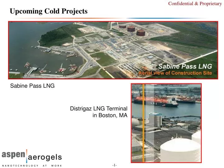
Upcoming Cold Projects. Sabine Pass LNG. Distrigaz LNG Terminal in Boston, MA. Cheniere Energy Trial. Insulation Incorporated: contractor Install on 36” line 80mm Cryogel system vs 9.5” (2 layer FOAMGLAS system) Results For large bore pipe and fittings: 80% faster install rate for Cryogel

E N D
Upcoming Cold Projects Sabine Pass LNG Distrigaz LNG Terminalin Boston, MA
Cheniere Energy Trial • Insulation Incorporated: contractor • Install on 36” line • 80mm Cryogel system vs 9.5” (2 layer FOAMGLAS system) • Results • For large bore pipe and fittings: 80% faster install rate for Cryogel • For small bore pipe and fittings: 10-20% faster install for Cryogel (note small bore applies when half sections are applied)
Cryogel Installation Demo at theDistrigas LNG Terminal Everett, MA October, 2007
LNG storage tanks Liquid and vapor lines Install location 24” line 12” line Moored position of boat Background Info On 1st Cryogel Installation by Suez LNG NA • Between Friday, October 12 and Tuesday, October 16, crews from Zampell Insulation installed foil-faced Cryogel on a section of piping at the Distrigas LNG terminal in Everett, MA Scope of work included two 26 ft pipe sections abutting sliding shoes: • 24” liquid transfer line • 12” vapor return line
Brush Pipe and Existing Vapor Stop with 90-66 Prior to 1st Piece Photo courtesy Zampell Insulation
Liquid Transfer Line Used 7 Layers (70 mm) Applied In 4 Pieces Photo courtesy Zampell Insulation
Every Vertical and Horizontal Seam Butyl Taped Photo courtesy Zampell Insulation
90-66 Application On Liquid Line Prior to 3rd Piece Photo courtesy Zampell Insulation
Installing 3rd Piece (Layers 5 and 6) On the Liquid Line Photo courtesy Zampell Insulation
Build Cryogel Up to Existing Vapor Stop Diameter At Each End Shoe diameter 10 inch Cryogel transition piece Cryogel diameter Photo courtesy Zampell Insulation
Vapor Stop From Existing Cellular Glass to Cryogel Photo courtesy Zampell Insulation
Finishing Up Liquid Line with Alumaguard Photo courtesy Zampell Insulation
Finished Aerogel Product On LNG and Vapor Lines Photo courtesy Zampell Insulation
Predictions Match Observed Behavior for All Four Systems* Freezing observed Condensation observed * Note that the IR camera used for this study (an Infracam SD from FLIR) does not compensate well for low-emissivity surfaces like Alumaguard. Therefore, although the relative temperature differences between observed surfaces are correct (particularly for surfaces imaged in the same frame), the absolute value of the temperature readings may not be accurate.
The Cryogel-Insulated Piping Performed As Designed Bare pipe HD foamglas shoes 24” LNG line Concrete pad 12” vapor line Shows extent of Cryogel insulated sections
70 mm Cryogel Matches Performance of 150 mm Cellular Glass 70 mm (2.75”) Cryogel 150 mm (6”) cellular glass
Summary and Conclusions • Despite some early delays re: the vapor stop specification and the most efficient cutting tools, the Cryogel system clearly offers productivity advantages • Faster installation • Ease-of-use in awkward or confined areas • Elimination of expansion / contraction joints • All the insulation systems near the dock behaved as expected, and showed no defects in either material or workmanship. These included: • 3” HD foamglas on the pipe shoes • 4” and 6” standard foamglas • 2.8” (7 layers of 10 mm) Cryogel 10201-Z • Note that the sections using 3” and 4” foamglas are clearly underinsulated
Uthmaniyah Gas Plant Saudi Arabia Size: 8” Fluid: NGL (C2+) Temperature: -90 oF Existing FOAMGLASS thickness: 150 mm.( Two layers of 75 mm, prefabricated pipe cover). Cryogel Thickness: 60 mm Cryogel install time: 15 minutes Cryogel Advantages: Reduction in the outside diameter of the insulated pipe thus less cladding material is used. No fabrication required and less install time required. Less accessories.
Ormen Lange Norway Trial Here you can see the space saving with used of Cryogel. 2x10mm. Here its used normal Insulation. Foamglass 50mm.
Technip cryogenic PIP • System qualified Bureau Veritas