Download
1 / 29
290 likes | 407 Views
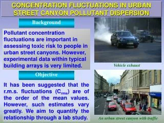
Gaseous And Particulate Dispersion In Street Canyons. Kambiz Nazridoust Department of Mechanical and Aeronautical Engineering Clarkson University, Potsdam, NY 13699-5725. Objectives.

E N D
Gaseous And Particulate Dispersion In Street Canyons Kambiz Nazridoust Department of Mechanical and Aeronautical Engineering Clarkson University, Potsdam, NY 13699-5725
Objectives • Develop A Numerical Model in FLUENT™ Code Coupled with Different Turbulence Models to Simulate the Fluid Flow, Pollutant Dispersion and Particle Deposition inside the Street Canyons • Examine the Accuracy of Major Turbulence Models with Experimental Data for Street Canyon Modeling • Examine Gaseous Air Pollution from Vehicular Exhaust and Industries inside the Street Canyons • Examine Particulate Transport and Deposition in Street Canyons for Different Particle Sizees and Flow Conditions
Vehicular Emission Line Source Q=4 lit/h Boundary Conditions Plane of Symmetry 1/7th power inlet velocity Outflow All walls: -No slip velocity boundary condition -Zero Diffusive Flux -Stick upon impact Leeward Windward
Governing Equations Continuity: Momentum: Reynolds Stress Transport Model:
Flow Field Results CO2 Concentration –Asymmetric Canyon Configuration
Flow Field Results Stream Functions(m2/s2) inside the Canyons for Different Wind Velocities
Flow Field Results Velocity Vector Field inside the Canyons for Different Wind Velocities
Flow Field Results CO2 Concentration inside the Canyons for Different Wind Velocities
Flow Field Results Turbulence Intensity(%) inside the Canyons for Different Wind Velocities
Wind Tunnel Experiment Measurement Points of Wind Tunnel Experiment by Meroney et al. (1996) Computational Grid of the Exact Dimensions of the Wind Tunnel Experiment
Comparison with Wind Tunnel Experiment (a) Leeward (b) Windward
Comparison with Wind Tunnel Experiment (a) 1st Roof (b) 2nd Roof
Particulate Emissions Leeward Windward Particulate Injector: -1000 Spherical Carbon Particles -0.013 m/s (for 4 lit/h volumetric flux) -3nm to 10micron All walls: -No slip velocity boundary condition -Stick upon impact
Particulate Emissions Motion of Spherical Particle Particle Relaxation time Stokes-Cunningham Slip Correction Factor Stokes Number Capture Efficiency
Particulate Deposition Patterns Particle Capture Efficiency vs. Particle Diameter for Different Surfaces (a) Windward Wall; (b) Leeward Wall; (c) Roofs; (d) Road
Particulate Deposition Patterns Particle Capture Efficiency vs. Stokes Number for Different Wind Velocities
Conclusions • The present simulation has reasonable agreement with the experimental data from wind tunnel experiment performed by Meroney et al (1996). • Among the turbulence models used in this study, Reynolds Stress Transport model (RSTM) shows better agreement with experiment in most of the cases. • For higher wind speeds less gaseous emission will happen on the walls of the buildings. • Particle transport and deposition on the surfaces depend on the wind speed and size of the particles. • Particle deposition is controlled by Brownian motion for low velocities and Gravity for large particles.