Download
1 / 38
380 likes | 473 Views
Annual Conference – Concord, NC November 12, 2013. A PRACTICAL APPrOACH TO p H controL :. Observations From Different Neutralization System Startups. Rob L. Rebodos, PhD Samanth E. Dawson, PE E . Matthew Fiss, PhD, PE Edward C. Fiss, Jr., PE. www.fissenvironmental.com.

E N D
Annual Conference – Concord, NC November 12, 2013 A PRACTICAL APPrOACHTO pH controL: Observations From Different Neutralization System Startups Rob L. Rebodos, PhD Samanth E. Dawson, PE E. Matthew Fiss, PhD, PE Edward C. Fiss, Jr., PE www.fissenvironmental.com
H2O H+ + OH- pH = -log [H+] Molar concentration (moles/L) www.raisingsparks.com pH Probe pH Meter www.microbmonitor.com pH buffers Can we translate simplicity of bench-scale pH measurement and control to full-scale systems???
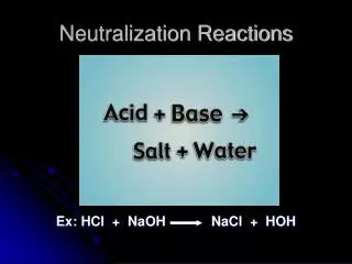
pH Control Systems • For many industrial facilities, the only pretreatment of process wastewater necessary prior to discharging to a municipal sewer system is simply pH neutralization.
Schematics of a SimplepH Control System Chemical Addition Reaction Tank Influent Wastewater Discharge • pH sensor and transmitter • Mixer
slightly ^ Schematics of a SimplepH Control System Chemical Addition Influent Wastewater Discharge Reaction Tank 2 Reaction Tank 1 • pH sensors and transmitter • Mixers
not so ^ Schematics of a SimplepH Control System Chemical Addition Influent Wastewater Discharge Reaction Tank 2 Reaction Tank 1 EQ Tank • pH sensors and transmitter • Mixers
Schematics of a SimplepH Control System Chemical Addition Influent Wastewater Final pH Adjustment Check Reaction Tank 2 Reaction Tank 1 EQ Tank • pH sensors and transmitter • Mixers Discharge Divert for Retreatment • In practice, however, a pH control system can be highly complex.
Schematics of a SimplepH Control System Chemical Addition Influent Wastewater Final pH Adjustment Check Reaction Tank 2 Reaction Tank 1 EQ Tank • pH sensors and transmitter • Mixers Discharge Divert for Retreatment • All individual components need to perform effectively at all times. • The control system should be designed properly to provide efficient neutralization even in extreme conditions.
Issues ConcerningpH Control System • Operation and maintenance of pH control system can sometimes be tiresome because of its complexity. • Common operational issues involve elaborate start-up procedures, rapid deterioration of components particularly when dealing with extreme conditions, and tedious maintenance of pH probes. • Proper design of pH control system could help avoid these issues. Some practical considerations observed during pH system startups are listed below to deal with some of these problems.
pH Probes • Weakest link in automatic pH control systems • Probes subject to continuous fouling when continuously immersed in wastewater stream • biological growth/fouling • chemical fouling • Need to clean and calibrate pH probes frequently (weekly) to avoid false pH signals and erroneous pH adjustment • Probes subject to periodic failure • causes overfeeding or underfeeding of chemicals based on false pH signal • Need to be able to detect probe failures and false pH readings
pH Probes Comparison pH Probe Testing Goal: Determine cost-effective and ideal pH probe for a specific wastewater pH adjustment system • Evaluation of commonly used pH probes was performed using three commercially available pH electrodes. • Two bulb type sensors and one flat-type electrode were used. • The pH probe testing was performed by submerging all electrodes in a synthetic softdrink plant wastewater.
pH Probes Comparison • A comparison of different pH probes was conducted to determine the ideal electrode for the softdrink plant wastewater pH control system. pH Probe Testing • Probes were evaluated based on: • Response Time • Signal Noise • Calibration Ease • Probe Installation Method • Probe Replacement
Response Time • For this study, a pH probe response time is defined as the amount of lapsed time (in seconds) after chemical addition before a stable reading is attained. • During this test, 15 readings per second were recorded, where voltage was measured across a 250 ohm resistor in the 4-20ma loop. The voltage was converted into pH using the following formula: pH = (mV/0.25) - 4)(0.875) • A reading was defined as being stable if the change in the average of 10 readings (over 0.67 seconds) is less than 0.01 pH units after filtering out noise.
pH changes were recorded during both acid addition and caustic addition resulting in pH swings from approximately pH 11 s.u. to pH 2 s.u. and back. During acid addition, Probe 1 and Probe 3 took turns stabilizing first, while Probe 2 stabilized after an average of 6 to 8 seconds later. During base addition, Probe 1 stabilized first, followed by the other probes in various order. • Readings from Probe 2 were observed to have wider range (max + 1.5 pH unit), as compared to + 0.5 pH unit for Probe 1 and + 0.3 pH unit for Probe 3. • Probe 1 had the fastest response time followed by Probe 3 while Probe 2 had the slowest response time.
Signal Noise • Signal Noise is defined as the lack of stability in the pH reading during pH adjustment. • Since the instantaneous reading is used to control chemical pump speeds, a signal with less noise allows the chemical feed rates to decrease more uniformly as the solution pH approaches the pH setpoint. • A small amount of excess reagent can cause a significant pH change at circumneutral pH, signal noise could lead to a significant overshooting of the pH setpoint. • Of all probes tested, Probe 3 had the least amount of signal noise while Probe 2 had the most signal noise and gave the most erratic readings.
Calibration Ease • Calibration is required to obtain accurate pH readings. Calibration is initiated by switching from measurement mode into calibration mode and submerging the probes in different buffers. • Probe 1 was the easiest to calibrate displaying the calibration slope (mV/pH unit) at the end of the process. Calibrating the other probes involved additional steps that were a little more complex to go through. Probe 3 calibration program has more built-in safeties that prevent operation when the slope is said to be out of range.
Probe Installation (Insertion method) • Probe 3 insertion method seemed better than the other probes. The probe can be installed directly through a weldalet or in a pipe tee or “Y” using a ball valve assembly kit. • Closing off with a stainless ball valve is better than the PVC assembly used for the other probes since it is expected to be operated regularly during probe replacement or maintenance.
Partial and Full Probe Replacements • Probe tip (partial) replacement • Electrode replacement and preamplifier replacement are most convenient for Probes 2 since the preamplifiers are separate from the electrodes themselves. • Probe 1 has built-in preamplifier, so the entire probe needs to be replaced if there are preamplifier issues. • The double junction salt bridge for Probe 3 is field replaceable, but like Probe 1, preamplifier issues mean that the entire probe needs to be replaced as well.
Partial and Full Probe Replacements • Whole Probe Replacement • In terms of whole probe replacement, Probe 3 stands out with a quick connect capability and can be easily dismantled because of the Variopol connector attached to the probe cable. • The other probes have cables that must to be re-pulled back to the analyzer or junction box and will need to be rewired each time the probe is replaced.
Comparison of Different pH Probes Tested Overall, the results of the pH probe testing suggest that the bulb-type probes were more superior than the flat-type probe in terms of response time, steadiness of reading, noise, and slope of pH change over time.
pH Electrode • Performance of pH electrodes varies depending on type and material of construction. Make sure that the pH electrode chosen is compatible with the influent wastewater to be treated. • Aside from choosing the right electrode, the pH sensor should be properly installed.The placement of the pH electrode in the reaction tank or effluent discharge piping could majorly affect the performance of the system. • One simple way to avoid electrical interference is to minimize distance between the electrode and controller.
pH Electrode • pH electrodes need to be regularly cleaned and calibrated to maintain accurate readings particularly those that are applied in aggressive environments. • In somes cases, cleaning and calibration requires removing the pH electrode from the reaction tank requiring process shutdown. • Whenever possible, in-line probe washing/flushing and calibration should be preferred because both allow pH electrode maintenance without causing disruption of process.
Equalization (EQ) Tank • Installing an equalization tank prior to the reaction tanks could minimized variability in wastewater characteristics making treatment more predictable. Chemical Addition Influent Wastewater Final pH Adjustment Check Reaction Tank 2 Reaction Tank 1 EQ Tank • pH sensors and transmitter • Mixers Discharge Divert for Retreatment
Reaction Tanks • The reaction tank should be sized accordingly to allow sufficient reaction time for neutralization. Chemical Addition Influent Wastewater Final pH Adjustment Check Reaction Tank 2 Reaction Tank 1 EQ Tank • pH sensors and transmitter • Mixers Discharge Divert for Retreatment • As observed in the facilities evaluated in this study, installing more than one reaction tank provides better process control.
Chemical Feed • The choice of chemicals for pH neutralization usually depends on the influent wastewater characteristics and the desired effluent pH range. Chemical Addition • For this specific application, since softdrink plant wastewater are mostly acidic, caustic solution is used to neutralize the influent wastewater. Influent Wastewater Final pH Adjustment Check Reaction Tank 2 Reaction Tank 1 EQ Tank • pH sensors and transmitter • Mixers Discharge Divert for Retreatment
Chemical Feed • In cases when the desired pH is exceeded, it was usually sufficient to lower the pH using carbon dioxide (CO2) rather than using an acid. • CO2is also safer to handle and cannot lower the wastewater pH below 5.5-6 s.u. which is usually the lower limit of the discharge in most of the plants. • By using CO2, accidental discharge of wastewater with pH lower than the pH limit, due to malfunctioning equipment for example, could be avoided.
Chemical Feed Control • Another operation to keep in mind is the control of chemical delivery to the reaction tank. • When using limit control, chemical dosing is at a constant rate which may result to overshooting or undershooting of feed. • Use proportional control instead: where the rate of chemical feed would be proportional to the deviation of the pH from the desired set point.
Chemical Feed Control • One thing to be avoided in controlling chemical feed is hunting of the relay which could potentially cause breakdown of pumps (and/or solenoid at times). • This is experienced when at a given setpoint, the chemical feed stops once a specific setpoint is reached. However, after sufficient mixing, the actual pH drops again re-initiating the chemical feed. • This on-off-on-off cycle could eventually lead to pump malfunction. • To correct for this problem, it is sometimes necessary to adjust the set point at a higher (or lower) value than the actual desired value.
Chemical Feed Control • One thing to be avoided in controlling chemical feed is hunting of the relay which could potentially cause breakdown of pumps (and/or solenoid at times). • To correct for this problem, it is sometimes necessary to adjust the set point at a higher (or lower) value than the actual desired value. • Consequently, it would be best to initiate feed and alarm relay circuit timer first when the pH set point is exceeded. By doing so, only after a user-set period in which the desired pH is not attained, would a system alarm be triggered.
System Startup • System commissioning should involve hydraulic and chemical stress testing along with a thorough check of all alarm conditions listed in a system alarm matrix. • Startup commissioning should always take place with clean water before introduction of wastewater to ensure all system components are operating as required and there are no leaks etc. in the system. • Although pH probes are usually calibrated at the factory before shipment, probes should always be field calibrated before the testing phase.
System Startup • One of the most important hydraulic design checks is to ensure that the system can push flows higher than the rated design without any overflow. The system should have adequate capacity to handle this peak flow and, in most cases, the system should be designed to handle 2 to 3 times the rated design flow. • As a rule of thumb, the system should be hydraulically designed to withstand flows when all influent pumps are running at capacity with a full or nearly full EQ tank (when present) to simulate a worst case scenario for system hydraulics.
System Startup • False alarms can usually be rectified on-site unless there is a structural element to them.
For example, the overflow alarm from the EQ tank was repeatedly triggered at or below the system design flows. • This was a result of wastewater backsplash from the flow in the normal discharge pipe triggering the overflow sensor located at a slightly higher elevation in the EQ tank primary overflow pipe. • The short term solution was to pull the sensor tip higher in the overflow pipe, with additional follow up testing to ensure that the alarm triggered normally as required during an overflow event. • The system design was modified during subsequent installations where the EQ overflow pipe was located a higher elevation from the discharge pipe to avoid this false alarm.
False Alarms • Other instances of false alarms that were encountered during system commissioning were during the pH probe wash operations. • At sites where the incoming potable water had a high pH, the momentary injection of a high pH water stream on the probes triggered a pH deviation alarm. • Usually the pH deviation alarms are timed to trigger at 10 seconds. • In this case the trigger time was set at a longer duration to allow the probes to read the correct pH of the wastewater after the probe flush.
Conclusions • For many industrial facilities, a simple pH adjustment for neutralization of their wastewater will suffice as a pretreatment method prior to discharging to a municipal sewer system. • Based on experiences from a number of system startups and commissioning, wastewater pH control is anything but simple. • Proper pH control system design begins by characterizing wastewater and choosing the correct components needed to achieve the required neutralization.
Conclusions • Performing a thorough Site Acceptance Tests (SAT) during startup and commissioning provided valuable insights to issues oftenly experienced in pH control systems. • Specific procedures that involved hydraulic and chemical stress testing, along with a thorough check of all alarm conditions listed in a system alarm matrix, proved to be valuable tools in preventing unnecessary plant downtime and avoiding costly and potentially catastrophic system failures.
Annual Conference – Concord, NC November 12, 2013 Thank you! For additional questions or comments, please feel free to contact: rob.rebodos@fissenvironmental.com ned.fiss@fissenvironmental.com www.fissenvironmental.com 7251 Pineville-Matthews Road, Suite 300 Charlotte, NC 28226