Download
1 / 33
330 likes | 334 Views
QC And NEMA In The Nuclear Arena. Gamma Cameras. Floods – Uniformity Testing. Types of floods Co57 Impregnated plastic Old source vs. the new source Refillable flood Adding the Tc99m Mixing and spilling It will bow if its too big Point source at least 5 diameters away from the surface

E N D
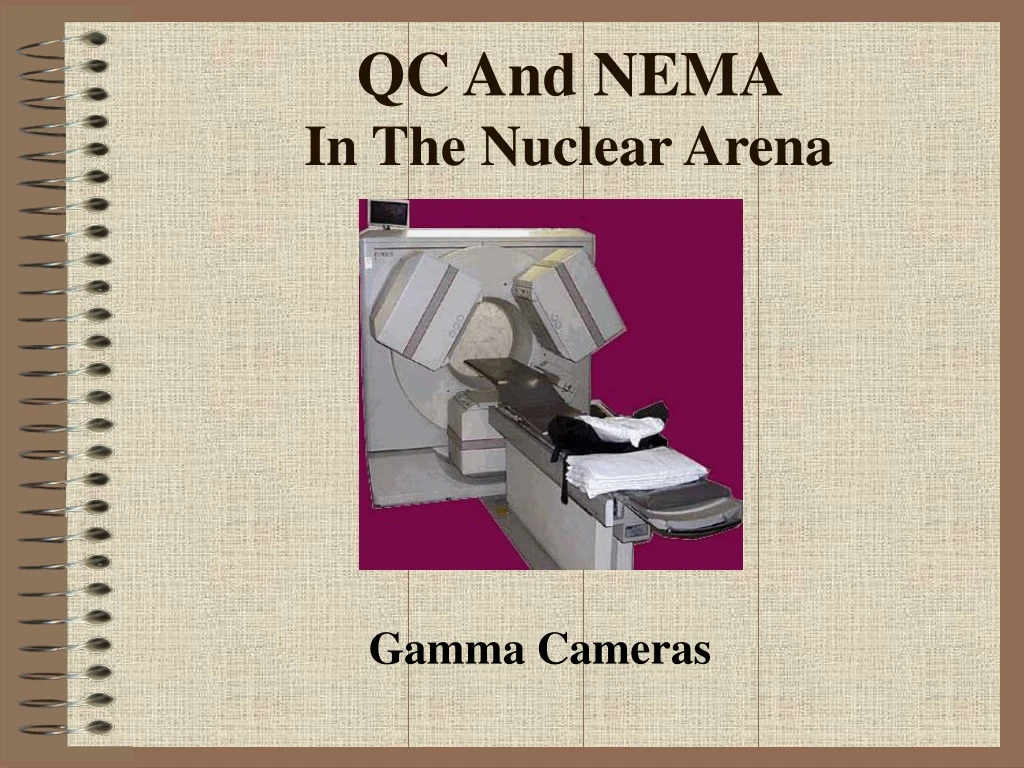
QC And NEMA In The Nuclear Arena Gamma Cameras
Floods – Uniformity Testing • Types of floods • Co57 • Impregnated plastic • Old source vs. the new source • Refillable flood • Adding the Tc99m • Mixing and spilling • It will bow if its too big • Point source at least 5 diameters away from the surface • Key Points • Setting the peak • How many millions of counts? • Size of the detector • Complete daily • Amount of activity
Corrected Vs. Uncorrected • Setting your correction matrix • Depends on SPECT • 30 M vs. 120 M vs. the size of the head • Do one for each radiopharmaceutical • Correction will either subtract or add counts • Take un/corrected flood and bars • Correction for each PMT is no more than 10% • Acquire at least once or month or when needed
Intrinsic Uniformity • Determine Integral and Differential Uniformity • Remove collimator place a 3mm Pb “ring” around the UFOV (example next side) • Set 20% window 99mTc with source (~200 μCi) 5 UFOV away • Set matrix at 64 x 64 to collect no more than 20,000 cps • Acquisition - center pixels must collect 4000counts/pixe; (~16 M count flood) • Complete a 9 pt smooth and calculate the following
What are we looking at? • Integral uniformity looks at maximum deviation for both CFOV and the UFOV • Differential uniformity looks at the maximum change of counts over a range of any 5 pixels in every column and row • Excessive changes in any of the numbers is an indication non-uniformity problems • Time to call service guy!
Flood Sources • Co57 Flood Source • Rectangular or Circular • 5 to 20 mCi • Non-uniformity at <1.0% • No mixing required – reduces • radiation exposure • Expensive since it must be • repurchased based on Co57 decay • Refillable Flood Phantom • Rectangular or Circular • Different sizes to fit a specific type of detector • Inject mCi amount of Tc99m • and mix in the water filled container • Concerns • Mixing can get messy • Radiation exposure when mixing • Air bubble will distort the image
Typical Bars – Four Quadrant • Multiple types of phantoms are available to match the size of the detector • Bars contain Pb embedded in plastic. • Bars attenuate the gamma radiation being emitted from the flood source • Bars vary in size within each quadrant • Is usually done with the collimator on • Known as an extrinsic bar • Tests system resolution • Imaging system should resolve between the 3rd and 4th smallest quadrant • Smallest bars are 2 mm, however, it depends on the type of 4 quadrant bar • purchased
Setting Up The Bar Phantom Comments • How would imagine resolution be effected by LEHS vs. LEHR collimation? • How does increased counts effect image resolution? • How often is this procedure done on the imaging system? • Why are the bars rotated every time this procedure is done?
Other Types of Bar Phantoms • BHR Test Pattern • Lead plate that is 3.2 mm thick • is placed between 2 sheets of • Plastic • Orthogonal-holes are then drilled • in an array pattern • Emission source can be extrinsic • or intrinsic (intrinsic usually done) • Clearly defines system resolution • Over the entire camera • Linearity also identified • PLES (Equally Spaced Parallel-Bar) • Phantom • Checks linearity and resolution • Phantom is placed with flood source • on top (just like the Bar and Flood) • 5 mm and 3 mm bars are available • Linearity is the key • X and Y axis- linearity is tested • Looking for a straight line • Lines should not be wavy
BHR Phantom Results Example of a BHR phantom with 2.5 cm orthogonal-holes
More On Bars • Do weekly and rotate each week • How many counts? • Size of detector • Increased counts improves resolution • Collimation • Changes in resolution can be seen and identifies a loss of system resolution • Intrinsic or extrinsic?
Systems Uniformity/Linearity/Resolution Uncorrected Flood And Bars 4000k/image Corrected Flood And Bars 4000k/image
Edge Packing • Intrinsic flood uses a mask on top of the crystal to • eliminate this artifact • Extrinsic flood may show this artifact
Setting The Peak • Centering the peak is essential • Off peaking causes imaging artifact • What would happen if you imaged a patient with Co57 with Tc99m on board?
Example Of Being Off-Peak • Creation of lesions in the liver • Could this lead to an inappropriate diagnosis?
Distance And Resolution • These images show the effect • of distance on image resolution • Surface vs. 1 inch • 2 inch vs. 3 inches • What conclusion can you make • when it comes to imaging a • patient? • Does count density also add to • this issue?
Problem With A PMT • What causes this artifact? • How do both image sets differ? • How might this effect the a patient’s diagnosis?
Problems With Liquid Filled Floods • Image on the left shows a flood that was note mixed completely • Image on the right shows an air bubble in the flood
Collimator Damage • Image on the right indicates damage to the collimator septa • Image on the left shows the effects of septa damage on a diagnostic study
More Issues • Inappropriate X/Y coordinates set on the a formatter • Cracked crystal
Types Of Bars A – Parallel-line equal-space (PLES) phantom: Small lead bars Test Camera’s spatial resolution. Two transmission images are Taken at right angles. Consider the Moire pattern B – Four quadrant bar phantom: Show wholes of equal size. The smallest bars can go down to 2 mm in size. C – Orthogonal-hole (OH) phantom Comes in different sizes (0.64 cm, 0.48 cm, and 0.32 cm Diameter spaced at 1 cm, 0.96 cm, and 0.64 cm respectively. Matching the lower end of system resolution is important.
Results Of Excessive Activity • Activity from the source should never exceed 20k/second • The image on the left shows the results of excessive activity • The image on the right is the same, however, the activity has been reduced to less than 20k per second
Intrinsic Uniformity • With a point source collect 64 x 64 flood where the center pixel receives a minimum of 4000 cts (16 million count flood) • Filter with a 9 point smooth • Integral uniformity is the maximum pixel deviation • Differential uniformity max change of cts over range of any 5 pixels in all rows and in all columns
Key Points • Identifies the amount of nonuniformity with all areas of the flood • Variations between un/corrected should be no greater than 15% • Should be done weekly to determine when the camera needs a PM • “Measles” occur when water gets into the crystal • Floods should be done with the collimator on to see if there are any defects in it • A crystals may crack when there is change of 8 degrees F • Room temperature should range between 40 and 110 degrees F
Measles • Image is off-peak • Loss of the hermetic seal causes water to enter and dissolve the crystal
System Sensitivity • Is a parameter of camera’s ability to efficiently detect the incident gamma with the collimator on • Changes in sensitivity result from • Nonuniformities in the crystal • Decreased energy resolution • Incorrect collimation • Improper setting of the PHA • Recording the time it takes to collect a Co57 flood corrected for decay will identify any change in system sensitivity
System Spatial Resolution • Is defined as camera’s ability to accurately determine the original location of a gamma ray on an X-Y plan with collimation
Moiré Pattern • http://www.sandlotscience.com/Guided_Tours/Tour1/Tour_5.htm • When a bar phantom is not lined (oriented) up septa in collimator this patter will occur • Bars travel at angle to the line of wholes (septa) in the collimator • This can be further seen on the next two slides
Moiré Continued Moiré seen on bar Images Bands represent the bars and the holes represent the septa Images across From each other Identify the pat- tern
Moiré Continued This shows a different moiré pattern because of the change In rotation of the bars to the collimator septa
Instrumentation and QC Consider the following procedures that involve QC and instrumentation • Uniformity Matrix • Floods and Bars • Other types of Bars - what is there purpose? • Linearity • Off peak or on peak • Effects of Distance on image resolution • Count density • PMT artifacts • Crystal artifacts • Collimator artifacts • Flood field artifacts
QC On The Dose Calibrator • Constancy • Accuracy • Linearity • Geometry Return to the Table of Content