Download
1 / 34
340 likes | 449 Views
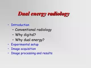
A silicon microstrip system with the RX64DTH ASIC for dual energy radiology. Introduction Why digital? Why dual energy? Experimental setup Image processing and results Alvarez-Macovski algorithm Subtraction imaging with contrast medium Conclusion and outlook. The Collaboration.

E N D
A silicon microstrip system with the RX64DTH ASIC for dual energy radiology • Introduction • Why digital? • Why dual energy? • Experimental setup • Image processing and results • Alvarez-Macovski algorithm • Subtraction imaging with contrast medium • Conclusion and outlook
The Collaboration 1) University of Eastern Piedmont and INFN, Alessandria, Italy L. Ramello; 2) University and INFN, Torino, Italy P. Giubellino, A. Marzari-Chiesa, F. Prino; 3) University and INFN, Ferrara, Italy; M. Gambaccini, A. Taibi, A. Tuffanelli, A. Sarnelli; 4) University and INFN, Bologna, Italy G. Baldazzi, D. Bollini; 5) AGH Univ. of Science and Technology, Cracow, Poland W. Dabrowski, P. Grybos, K. Swientek, P. Wiacek; 6) University of Antwerp, Antwerp, Belgium P. Van Espen; 7) Univ. de los Andes, Colombia C. Avila, J. Lopez Gaitan, J.C. Sanabria; 8) CEADEN, Havana, Cuba A.E. Cabal,C. Ceballos, A. Diaz Garcia; 9) CINVESTAV, Mexico City, Mexico L.M. Montano;
Introduction: why digital ? • Digital radiography has well known advantages over conventional screen-film systems • Enhance detecting efficiency w.r.t. screen-film • Image analysis • Easy data transfer
Based on different energy dependence of different materials Enhance detail visibility (SNR) Decrease dose to the patient Decrease contrast media concentration Introduction: why dual energy ? • Dual energy techniques • GOAL: improve image contrast
E 15-20 keV: Signal from cancer tissue deteriorated by the adipose tissue signal E 30-40 keV Cancer tissue not visible, image allows to map glandular and adipose tissues Example 1: dual energy mammography
Dramatic change of iodine absorption coeff. at K-edge energy (33 keV) Image subtraction (2 images taken below and above the K-edge energy) Example 2: angiography at the iodine K-edge Iodine injected in patient vessels acts as radio-opaque contrast medium
Quasi-monochromatic beams • ordinary X-ray tube + mosaic crystals • instead of truly monochromatic synchrotron radiation • Advantages: cost, dimensions, availability in hospitals • Linear array of silicon microstrips + electonics for single photon counting • Binary readout • 1 or 2 discriminators (and counters) per channel • Integrated counts for each pixel are readout • Scanning required to build 2D image Experimental setup • To implement dual energy imaging we need: • a dichromatic beam • a position- and energy-sensitive detector
Experimental setup: beam (1) Bragg Diffraction on Highly Oriented Pyrolitic Grafite Crystal 1st and 2nd Bragg harmonics E and 2E are obtained in the same beam Collimator W anode tube
Experimental setup: beam (2) Bragg Diffraction on Highly Oriented Pyrolitic Grafite Crystal Two spatially separated beams with different energies E-DE and E+DE obtained in 2 separate beams Double slit collimator W anode tube
incident spectra at 3 energy settings … More on the dichromatic beam … spectra after 3 cm plexiglass (measured with HPGe detector)
X-rays N. I. I/O cards PCI-DIO-96 and DAQCard-DIO-24 current pulses 100 m data, control Silicon strip detector Integrated circuit PC Experimental seup: Single Photon Counting System • Fully parallel signal processing for all channels • Binary architecture for readout electronics • 1 bit information (yes/no) is extracted from each strip • Threshold scans needed to extract analog information • Counts integrated over the measurement period transmitted to DAQ
Experimental setup: silicon detector Designed and fabricated by ITC-IRST, Trento, Italy
Detector efficiency • Efficiency calculation • X-ray absorbed if interacts in passive regions • X-ray detected if makes photoelectric effect in active regions • Front geometry • Strip orthogonal to the beam • 70 mm of Al light shield • Edge-on geometry • Strip parallel to the beam • 765 mm of inactive Si • Better efficiency for E > 18 keV
Detector 1 2 5 4 3 Experimental setup: RX64 chip Cracow U.M.M. design - (28006500 m2) - CMOS 0.8 µm process (1) 64 front-end channels a) preamplifier b) shaper c) 1 or 2 discriminators (2) (1 or 2)x64 pseudo-random counters (20-bit) (3) internal DACs: 8-bit threshold setting and 5-bit for bias settings (4) internal calibration circuit (square wave 1mV-30 mV) (5) control logic and I/O circuit (interface to external bus)
Experimental setup: PCB detector pitch adapter ASICs • PCB: • - One 400 strip detector • - Pitch adapter • - 6 RX64 chips • 384 equipped channels - connector to DAQ card 2 protoype detectors: • 6 x Single threshold RX64 • 6 x Dual threshold RX64
System calibration setup in Alessandria Fluorescence target (Cu, Ge, Mo, Nb, Zr, Ag, Sn) Detector in Front config. Cu anode X-ray tube → X-ray energies = characteristic lines of target material
Mo K Sn K Ge K Ag K Cu K MoK Ag K Rb Ka Sn K System calibration 241Am source with rotary target holder (targets: Cu, Rb, Mo, Ag, Ba) Cu-anode X-ray tube with fluorescence targets (Cu, Ge, Mo, Ag, Sn)
Dual energy imaging • K-edge subtraction imaging with contrast medium • Cancel background structures by subtracting 2 images taken at energies just below and above the K-edge of the contrast medium • Suited for angiography at iodine (gadolinium) K-edge • Cancel background structures to enhance vessel visibility • Possible application in mammography (study vascularization extent) • Hypervascularity characterizes most malignant formations • Dual energy projection algorythm • Make the contrast between 2 chosen materials vanish by measuring the logarithmic transmission of the incident beam at two energies and using a projection algorithm [Lehmann et al., Med. Phys. 8 (1981) 659] • Suited for dual energy mammography • remove contrast between the two normal tissues (glandular and adipose), enhancing the contrast of the pathology • Single exposure dual-energy mammography reduces radiation dose and motion artifacts
X-ray tube with dual energy output Phantom Detector box with 2 collimators Angiography setup • X-ray tube + mosaic crystal and 2 collimators to provide dual-energy output • - E1= 31.5 keV, E2 =35.5 keV (above and below iodine k-edge) • Detector box with two detectors aligned with two collimators • Step wedge phantom made of PMMA + Al with 4 iodine solution filled cavities of 1 or 2 mm diameter
E = 31.5 keV E = 35.5 keV logarithmic subtraction Phantom structure not visible in final image Angiographic test results (I)
Conc = 370 mg / ml Conc = 92.5 mg / ml Conc = 23.1 mg / ml Possible decrease of iodine concentration keeping the same rad. dose Angiographic test results (II)
Dual Energy Angiography Digital Subtraction Angiography smaller cavity (=0.4 mm) visible in DEA and not in DSA Results with a second phantom Phantom Iodine conc. = 95 mg/ml
Dual energy projection algorithm The mass attenuation coefficient μ of any material at a given energy E is expressed as a combination of the coefficients of any two suitable materials and : The logarithmic attenuation M = μξtξ of the material of thickness tξ is measured at two different energies: low (El) and high (Eh): A1 and A2 represent the thicknesses of the two base materials which would provide the same X-ray attenuation as material ξ.
Dual energy projection algorithm I0 ξ ψ R I1 I2 M1 C 90° C 1 The logarithmic attenuation M in a given pixel can be represented as a vector having components A1 and A2 in the basis plane, the modulus will then be proportional to the gray level of that pixel If a monochromatic beam of intensity I0 goes through material ξwhich is partly replaced by another material ψ … … then the vertexes of log. attenuation vectors M2 (material ξ) and M1 (mat. ξ+ψ) lie on a line R which is defined only by the properties of materials α, β, ξandψ. Projecting along direction C, orthogonal to R, with the contrast cancellation angle : M2 A2 2 … it is possible to cancel the contrast between materials ξand ψ: both M1 and M2 will project to the same vector A1
Mammographic phantom • Three components: polyethylene (PE), PMMA and water to simulate the attenuation coeff. m (cm-1) of the adipose, glandular and cancerous tissues in the breast S. Fabbri et al., Phys. Med. Biol. 47 (2002) 1-13
Correct for: HE and LE images 16 keV 32 keV • pixels with huge n. of counts (bad counter conversion) • dead pixels • X-ray beam fluctuations • subtract high threshold image from low threshold one • correct for spatial inhomogeneities of beam and detector extracted from flat-field profiles Image processing (1) Measured (raw) Low thr. High thr.
Image processing (2) 16 – 32 keV 18 – 36 keV 1= PMMA 2=water 3=PE 4=(water+PE) • Low statistics due to: • 2nd order harmonic • dectecting efficiency
Top View Side View Simulation with MCNP • MCNP-4C simulation with • ENDF/B-VI library • Photons and electrons tracked through the phantom and the detector (including the inactive region in front of the strips) • Energy deposition in each strip recorded • histogram of counts vs. strip number filled 1=detector 2=PMMA 3=water 4=PE
simulation 16 – 32 keV Experiment vs. Simulation (1) RX64DTH 16 – 32 keV
MCNP simulation RX64DTH 16 – 32 keV Results (1): SNR vs. proj. angle Theoretical cancellation angles: PMMA-water 36.5° PE-water 40.5° PMMA-PE 45° Cancellation angle for a pair given by SNR=0
Results (2): SNR summary * Previous version of ASIC, exposure with about 2x more incident photons
PMMA-water cancellation PMMA-PE cancellation Results (3): Projected images RX64DTH 16 – 32 keV simulation 16 – 32 keV
Conclusion and Outlook • We have developed a single photon counting silicon detector equipped with the RX64DTH ASIC, with two selectable energy windows • The energy resolution of 0.8 keV (rms) is well adapted for dual energy mammography and angiography • We have performed mammography imaging tests with a three-material phantom • We have demonstrated the feasibility of contrast cancellation between two materials, enhancing the visibility of small features in the third one • We have performed angiography imaging tests with 2 different phantoms and iodine contrast medium • We have demonstrated the feasibility of logarithmic subtraction between two images, enhancing contrast of small vessels also with lower iodate solution concentrations • OUTLOOK: • Increase photon statistics at high energy, optimize exposure conditions • New detector materials, CZT? • Tests with a more realistic mammographic phantom