Download
1 / 46
480 likes | 534 Views
Construction Documents. Introduction Construction Documents Correlation Between Drawings and Specifications Construction Drawings Construction Specifications Project: Site Plan & Floor Plan. Introduction.

E N D
Construction Documents • Introduction • Construction Documents • Correlation Between Drawings and Specifications • Construction Drawings • Construction Specifications • Project: Site Plan & Floor Plan
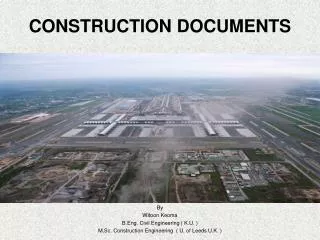
Introduction • Construction Documents prepared by architects and their consultants consists of drawings and specifications. • The function of these documents is to convey the design intent to the contractor for bidding and construction. • It is therefore important that CD’s are… • clear / concise / correct / coordinated
Correlation Between Drawings and Specifications • Drawings • Define the physicalrelationships between materials, products and systems • They indicate dimensions & locations • Sizes, quantities and configurations are on the drawings
Correlation Between Drawings and Specifications • Specifications • Specifications express in writing, the requirements regarding quality • They outline the products, materials and fabrication • They explain material and product testing requirements as well as erection and installation criteria
Construction Drawings • Drawing Conventions • A logical system for organizing drawings and drawing sets • Material designations • Drawing symbols • Standard abbreviations • Schedule formats
Construction Drawings • Drawing Sequence & Numbering System • Title Sheet, materials list, abbreviations, symbols, notes T-01 • Architectural Drawings A-01 • Structural Drawings S-01 • Plumbing Drawings P-01 • HVAC Drawings M-01 • Electrical Drawings E-01
Construction Drawings • Clarity=Common Sense + Coordination • Incomplete Drawings • Generate lots of ????’s • Produce un-intended results • Inaccurate Drawings • Generate lots of field errors • Cost lots of $$$ • Avoid • Redundant information • Omissions • Unnecessary information
Construction Drawings • Shop Drawings & Submittals • Architects drawings show design intent only • They are not supposed to be 100% complete • Contractors achieve the design intent by making the selections based on the drawings • Contractorssubmits shop drawings and other related information (product data and samples) to the architect • The architect approves these submittals for compliance with design intent only • This topic is discussed later in the course in more detail
Construction Specifications • All of the written documentation for a project is found in the project manual: • Bid Forms and Instructions to bidders • Owner – Contractor Agreement • Conditions for Construction • Miscellaneous Forms • Project Specifications
Construction Specifications Institute (CSI) • Specifications define the qualitative requirements of materials and products. • The Construction Specifications Institute (CSI) has developed a numbering and titling format used to organize all construction information including specifications. • The MasterFormat, provides a means of coordinating that information with a contractor's submittals, cost accounting systems, material filing, and requests for interpretation. • http://www.csinet.org
Site Plans • Site plans are generally started very early in the process of preparing a set of construction documents. • This helps the consultants on the job by providing them with information that is necessary for their work to progress. • It also helps the architect by getting some of the drafting work done before the final phase of the project. • Site plans generally do not contain a great deal of cross-references to other drawings in the document set, but they do contain references to a number of details that will need to be prepared for the detail sheet or book
Site Plans - General Information • Site plans can be among the simplest or the most complex construction drawings to execute. The degree of difficulty will depend on the extent of work that the architect chooses to do personally. • There are 3 distinct parts to a site plan • the architectural site plan • the landscape site plan • the grading site plan. • One or all of these site plans may be done by the architect; separate sheets may be required.
architectural site plan • The architectural site plan shows features of the site that are of architectural importance, as opposed to features that would be important for landscaping or grading purposes. • Also included would be engineering features that would have an architectural impact, such as transformers, exterior lighting, fire hydrants, and so forth.
landscape site plan • The landscape site plan shows features that are of importance to the landscaping contractor. A listing of all plant materials should be included that shows plant type, size, and quantity desired. Notes covering the fates of existing trees and shrubs should also be included. • On some simpler projects this plan may be combined with the architectural site plan. Frequently, however, this drawing will be prepared by an outside consultant and will not be included as a construction document that is prepared by the architect
grading site plan • The grading site plan shows the grading aspects of the site. On certain simpler projects this plan may be combined with the architectural site plan. Frequently, however, the grading site plan will be prepared by an outside consultant and will not be included as a construction document supplied by the architect. • The grading site plan also must include two general notes. • The first note provides the date that the survey for the site was per formed and the name of the group that did the work. • The second note makes reference to the soils report for the project, stating that the report, although not bound into the construction documents, is considered a part of the set
Drawing the Site Plan - General • When drafting a site plan, you should imagine taking an aerial photograph of the site. The exception to this view is the building itself. • Although some architects like to draft the roof of the building onto the site plan and thus remove the need to draft a separate roof plan, it is preferable to separate the two drawings for a clearer presentation. • When using this method, you should draft a heavy outline of the building's footprint onto the site plan
Drawing the Site Plan - Scale • Site plans should be shown at a scale that will provide an adequate and clear presentation of all of the required information. • You should note that site plans make use of engineers' scales instead of architects' scales. • Appropriate scales include, but are not limited to, l" = 20'-0"and 1" = 40'-0".
Drawing the Site Plan - Dimensioning • In dimensioning site plans it is typical to use decimal notation rather than feet and inches. • Using decimal notation will also make it easier for you to cross-reference the numerous types of site plans. • Dimensions indicated should be the actual dimensions
Drawing the Site Plan - Orientation • Site plans should always be oriented on a sheet in such a way that the north arrow is pointing either up or to the right (pointing up is the most typical orientation). This is the convention in the building and engineering professions. • The site plan should be located slightly above and to the right of the center of the sheet. This allows space at the bottom of the sheet for notes to be added if necessary
Appropriate Notes and Symbols These notes and symbols are broken into two categories: architectural site plan and grading site plan. Architectural Site Plan The property line for the site should be shown as a series of long heavy lines with two dashes.The information concerning the location of the property line should be taken from the site survey. A heavy outline of the building's footprint should be shown. The finished floor elevation of the ground level should be labeled inside of this footprint with a bullet. All names of streets that adjoin the property should be labeled. All utility lines as well as power poles, transformers, traffic signal's and manholes should be copied from the survey onto the site plan. All concrete walks should have their expansion joints drafted labeled "EJ”. Contraction joints should also be drafted but need not be labeled.
Dimensions should be in generally continuous strings(ones that run for more or less the entire length of the drawing). Short strings should be avoided. Dimension strings that are intended to locate the building should intersect the property lines to give them a logical frame of reference. Dimension strings for other site features should intersect either the building or the property lines.
Phase I As is the case with all construction documents, the first phase of the drawing usually requires the most actual drafting. The plus side of this is the fact that most of this initial work is relatively easy, as it is primarily an execution of known items from the design phase of the project. The Phase I drawing shows the site and its property lines as well as the surrounding roadways. The general configuration of the parking is also shown. At this point the only architectural site feature shown is the preliminary outline of the concrete walk. The drawing is next given its title and scale, and information in the title block is filled in properly. With this information complete, the site plan is now at a stage of completion that will allow the engineering consultants to begin more serious work on their parts of the construction document set.
Phase 2 The second phase of the site plan documentation reflects a substantial step forward in terms of drawing refinement. The parking areas are completed and dimensioned (including radius information). The concrete walks are dimensioned and noted, and some of the architectural features such as benches are added. Engineering features that will have a direct impact on the architectural nature of the project are added to the drawing at this stage. These include the locations of the transformer as well as site lighting.
Phase III Phase 3 reflects the addition of notes, detail cuts, and material indications. The amount of work needed to do material indications for a site plan is modest. If time is a constraint, material indications can be eliminated. Detail cuts refer to details that would be drafted concurrent to the completion of the site plan. We are assuming that the grading for the site is by an outside consultant. Therefore, references to items such as manholes and catch basins are not included. If the grading were to be incorporated onto the architectural site plan, these items would need to be included.
Completed Site Plan • Miscellaneous notes are also added during this phase of the drawing. Included are the references to the soils report and to the survey. • It is important to include descriptions of any items that might not have been detailed previously due to time constraints. The reason for this is simple: • When a set of construction documents is released for bid, the contractor estimates how much the project will cost to build based on the construction documents and the project specification. • Typically, a contractor will be hired based on the bid that is given. Contractors are reluctant to "give away" items that were not originally included in the construction documents. • Neither are owners generally anxious to spend more than the amount that was originally set forth in the contractor's bid. • By including notes about un-detailed items, the architect is assured that an allowance will be made for each item, and that items will not have to be eliminated because of an oversight. • You should check all documents at their final phase of completion, verifying all dimension strings and detail references.
Assignments • Read Lesson 2 pp 1-23 • Site Plan and Start of Floor Plan