Download
1 / 39
721 likes | 1.66k Views
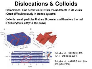
DISLOCATIONS. Edge dislocation Screw dislocation. Plastic Deformation in Crystalline Materials. Creep Mechanisms. Slip (Dislocation motion). Twinning. Phase Transformation. Grain boundary sliding. Vacancy diffusion. Dislocation climb. Plastic deformation of a crystal by shear. m.

E N D
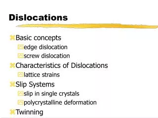
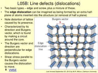
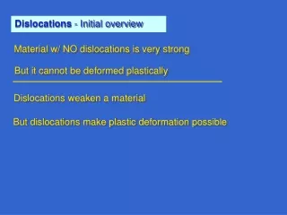
DISLOCATIONS • Edge dislocation • Screw dislocation
Plastic Deformation in Crystalline Materials Creep Mechanisms Slip(Dislocation motion) Twinning Phase Transformation Grain boundary sliding Vacancy diffusion Dislocation climb
Plastic deformation of a crystal by shear m Sinusoidal relationship Realistic curve
As a first approximation thestress-displacement curve can be written as At small values of displacementHooke’s law should apply For small values of x/b Hence the maximum shearstress at which slip should occur If b ~ a
The shear modulus of metals is in the range 20 – 150 GPa • The theoretical shear stress will be in the range 3 – 30 GPa • Actual shear stress is 0.5 – 10 MPa • I.e. (Shear stress)theoretical > 100 * (Shear stress)experimental!!!! DISLOCATIONS Dislocations weaken the crystal
Carpet Pull
DISLOCATIONS EDGE SCREW MIXED • Usually dislocations have a mixed character and Edge and Screw dislocations are the ideal extremes DISLOCATIONS Random Structural • Geometrically necessary dislocations
Dislocation is a boundary between the slipped and the unslipped parts of the crystal lying over a slip plane Slippedpartof thecrystal Unslippedpartof thecrystal
Burgers Vector Edge dislocation Crystal with edge dislocation Perfect crystal RHFS: Right Hand Finish to Start convention
Edge dislocation Direction of t vectordislocation line vector Direction of b vector
Dislocation is a boundary between the slipped and the unslipped parts of the crystal lying over a slip plane • The intersection of the extra half-plane of atoms with the slip planedefines the dislocation line (for an edge dislocation) • Direction and magnitude of slip is characterized by the Burgers vectorof the dislocation (A dislocation is born with a Burgers vector and expresses it even in its death!) • The Burgers vector is determined by the Burgers Circuit • Right hand screw (finish to start) convention is used for determiningthe direction of the Burgers vector • As the periodic force field of a crystal requires that atoms must move from one equilibrium position to another b must connect one lattice position to another (for a full dislocation) • Dislocations tend to have as small a Burgers vector as possible
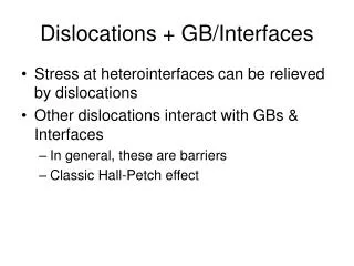
The edge dislocation has compressive stress field above and tensile stress field below the slip plane • Dislocations are non-equilibrium defects and would leave the crystal if given an opportunity
Compressive stress field Tensile stress field
STRESS FIELD OF A EDGE DISLOCATION X – FEM SIMULATED CONTOURS FILM 28 Å SUBSTRATE b 27 Å (MPa) (x & y original grid size = b/2 = 1.92 Å)
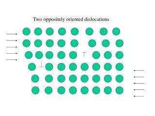
Positive edge dislocation Negative edge dislocation ATTRACTION Can come together and cancelone another REPULSION
Motion of dislocations On the slip plane Conservative (Glide) Motion of Edge dislocation Motion of dislocation to the slip plane Non-conservative(Climb) • For edge dislocation: as b t→ they define a plane → the slip plane • Climb involves addition or subtraction of a row of atoms below the half plane ► +ve climb = climb up → removal of a plane of atoms ► ve climb = climb down → addition of a plane of atoms
Edge Dislocation Glide Shear stress Surfacestep
Edge Climb Positive climb Removal of a row of atoms Negative climbAddition of a row of atoms
Screw dislocation [1] [1] Bryan Baker chemed.chem.purdue.edu/genchem/ topicreview/bp/materials/defects3.html -
Screw dislocation cross-slip Slip plane 2 b Slip plane 1 The dislocation is shown cross-slipping from the blue plane to the green plane
The dislocation line ends on: The free surface of the crystal Internal surface or interface Closes on itself to form a loop Ends in a node • A node is the intersection point of more than two dislocations • The vectoral sum of the Burgers vectors of dislocations meeting at a node = 0
Mixed dislocations t b b Pure Edge Pure screw
Motion of a mixed dislocation [1] We are looking at the plane of the cut (sort of a semicircle centered in the lower left corner). Blue circles denote atoms just below, red circles atoms just above the cut. Up on the right the dislocation is a pure edge dislocation on the lower left it is pure screw. In between it is mixed. In the link this dislocation is shown moving in an animated illustration. [1] http://www.tf.uni-kiel.de/matwis/amat/def_en/kap_5/backbone/r5_1_2.html
Energy of dislocations • Dislocations have distortion energy associated with them • E per unit length • Edge → Compressive and tensile stress fieldsScrew → Shear strains Elastic E Energy of dislocation Non-elastic (Core) ~E/10 Energy of a dislocation / unit length G → () shear modulus b → |b|
Dislocations will have as small a b as possible b→ Full lattice translation Full Dislocations(in terms of lattice translation) b→ Fraction of lattice translation Partial
Dissociation of dislocations Consider the reaction: 2b → b + b Change in energy: G(2b)2/2 → 2[G(b)2/2] G(b)2 The reaction would be favorable
(111) (111) FCC (111) Slip plane Some of the atoms are omitted for clarity → + Shockley Partials b12 > (b22 + b32) ½ > ⅓
FCC Pure edge dislocation The extra- “half plane” consists of two ‘planes’ of atoms
Dislocation line vector Burger’s vector Extra half plane Slip plane BCC Pure edge dislocation
Dislocations in Ionic crystals • In ionic crystals if there is an extra half-plane of atoms contained only atoms of one type then the charge neutrality condition would be violated unstable condition • Burgers vector has to be a full lattice translation CsCl → b = <100> Cannot be ½<111>NaCl → b = ½ <110> Cannot be ½<100> • This makes Burgers vector large in ionic crystalsCu → |b| = 2.55 ÅNaCl → |b| = 3.95 Å CsCl
Formation of dislocations (in the bulk of the crystal) • Due to accidents in crystal growth from the melt • Mechanical deformation of the crystal • Annealed crystal: dislocation density () ~ 108 – 1010 /m2 • Cold worked crystal: ~ 1012 – 1014 /m2
Burgers vectors of dislocations in cubic crystals Crystallography determines the Burgers vector fundamental lattice translational vector lying on the slip plane “Close packed volumes tend to remain close packed,close packed areas tend to remain close packed &close packed lines tend to remain close packed”
Slip systems Anisotropic No clear choice Wavy slip lines
Role of Dislocations Deformation Processes Diffusion(Pipe) Creep Fatigue Fracture Slip Structural Incoherent Twin Grain boundary(low angle) Semicoherent Interfaces Disc of vacancies ~ edge dislocation