Download

1 / 45
710 likes | 1.37k Views
Unit - 4. rolling. In metalworking, rolling is a metal forming process in which metal stock is passed through a pair of rolls. Definition of Rolling : The process of plastically deforming metal by passing it between rolls.

E N D
Unit - 4 rolling
In metalworking, rolling is a metal forming process in which metal stock is passed through a pair of rolls.
Definition of Rolling : The process of plastically deforming metal by passing it between rolls. • Rolling is the most widely used forming process, which provides high production and close control of final product. • The metal is subjected to high compressive stresses as a result of the friction between the rolls and the metal surface.
Rolling is the most extensively used metal forming process and its share is roughly 90% • The geometry of the product depend on the contour of the roll gap
Classification of Rolling Process i) Hot Rolling ii) Cold Rolling iii) Powder Rolling
Hot Rolling: • Hot working ---- above the re-crystallization temperature • It is employed where large reduction in cross-sectional area is required. • Used for bars, rods, rails etc. Cold Rolling: • Cold working ---- below the re-crystallization temperature • Employed for finishing the metal to given specification of sizes and surface quality. • Produces sheets, strips and foils with good surface finish and increased mechanical strength.
Powder Rolling: • Metal powder is introduced between the rolls and turned into a “green strip” which is subsequently sintered to high density. • This produces a tough sheet with very fine grain size or minimum of preferred orientation.
Terminology • Semi finished products • Bloom is the product of first breakdown of ingot (cross sectional area > 230 cm2 ) • Billet is the product obtained from a further reduction by hot rolling ( cross sectional area > 40x40 mm2 ) • Slab is the hot rolled ingot ( cross sectional area > 100 cm2 and width > 2 x thickness ) • Mill products • Plate is the product with a thickness > 6mm • Sheet is the product with a thickness < 6mm and width > 600mm • Strip is the product with a thickness <6mm and width < 600mm
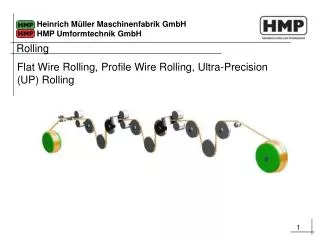
Rolling Process: • In the process of rolling the billet is fed from one side into the rolls and reduces in thickness according to the section and gap between the rolls. • The reduction ratios have maximum allowable values for different metals beyond which reduction is not practicable in a single process. • Rolling sets in series may be employed. ** There are fundamentally two types of rolls: • Supporting rolls • Driving rolls ** the rolls must be rigid or the rolled material will have a loop like shape.
ROLLING MILLS: • A rolling mill consists basically of rolls, bearings, a housing for containing these parts, and a drive for applying power to the rolls and controlling there speeds. • Rolling mills can be conventionally classified with respect to the number and arrangement of the rolls. Classification of rolling mills: • Two-high mills • Two-high reversing mills • Three-high mills • Four-high mills • Cluster mills • Continuous mills • Planetary mills
Continuous rolling • Use a series of rolling mill and each set is called a stand. • The strip will be moving at different velocities at each stage in the mill. • The speed of each set of rolls is synchronised so that the input speed of each stand is equal to the output speed of preceding stand. • The uncoiler and windup reel not only feed the stock into the rolls and coiling up the final product but also provide back tension and front tension to the strip.
Planetary mill • Consist of a pair of heavy backing rolls surrounded by a large number of planetary rolls. • Each planetary roll gives an almost constant reduction to the slab as it sweeps out a circular path between the backing rolls and the slab. • As each pair of planetary rolls ceases to have contact with the work piece, another pair of rolls makes contact and repeat that reduction. • The overall reduction is the summation of a series of small reductions by each pair of rolls. Therefore, the planetary mill can hot reduces a slab directly to strip in one pass through the mill. • The operation requires feed rolls to introduce the slab into the mill, and a pair of planishing rolls on the exit to improve the surface finish.
Different types of rolling processes • Continuous rolling • Transverse rolling • Shaped rolling or section rolling • Ring rolling • Powder rolling • Continuous casting and hot rolling • Thread rolling
Transverse rolling • Using circular wedge rolls. • Heated bar is cropped to length and fed in transversely between rolls. • Rolls are revolved in one direction.
Shaped rolling or section rolling • A special type of cold rolling in which flat slap is progressively bent into complex shapes by passing it through a series of driven rolls. • No appreciable change in the thickness of the metal during this process. • Suitable for producing moulded sections such as irregular shaped channels and trim.
Powder rolling • Metal powder is introduced between the rolls and compacted into a ‘green strip’, which is subsequently sintered and subjected to further hot-working and/or cold working and annealing cycles. • Advantage : • Cut down the initial hot-ingot breakdown step (reduced capital investment). • Economical - metal powder is cheaply produced during the extraction process. • Minimise contamination in hot-rolling. • Provide fine grain size with a minimum of preferred orientation.
Continuous casting and hot rolling • Metal is melted, cast and hot rolled continuously through a series of rolling mills within the same process. • Usually for steel sheet production.
Thread rolling • Dies are pressed against the surface of cylindrical blank. As the blank rolls against the in-feeding die faces, the material is displaced to form the roots of the thread, and the displaced material flows radially outward to form the thread's crest. • A blank is fed between two grooved die plates to form the threads. • The thread is formed by the axial flow of material in the work piece. The grain structure of the material is not cut, but is distorted to follow the thread form. • Rolled threads are produced in a single pass at speeds far in excess of those used to cut threads. • The resultant thread is very much stronger than a cut thread. It has a greater resistance to mechanical stress and an increase in fatigue strength. Also the surface is burnished and work hardened
Fundamental concept of metal rolling 1) The arc of contact between the rolls and the metal is a part of a circle. 2) The coefficient of friction, µ , is constant in theory, but in reality µ varies along the arc of contact. 3) The metal is considered to deform plastically during rolling. 4) The volume of metal is constant before and after rolling. In practical the volume might decrease a little bit due to close-up of pores. 5) The velocity of the rolls is assumed to be constant. 6) The metal only extends in the rolling direction and no extension in the width of the material. 7) The cross sectional area normal to the rolling direction is not distorted.
Forces and geometrical relationships in rolling • A metal sheet with a thickness h0 enters the rolls at the entrance plane xx with a velocity v0. • It passes through the roll gap and leaves the exit plane yy with a reduced thickness hf and at a velocity vf • Given that there is no increase in width, the vertical compression of the metal is translated into an elongation in the rolling direction. • Since there is no change in metal volume at a given point per unit time throughout the process, therefore ………. Eq. 1 Where b is the width of the sheet v is the velocity at any thickness h intermediate between h0 and hf
From Eq. 1 Given that b0 = bf Then we have When h0 > hf , we have v0 < vf …… Eq. 2 The velocity of the sheet must steadily increase from entrance to exit such that a vertical element in the sheet remain undistorted
At only one point along the surface of contact between the roll and the sheet, two forces act on the metal: 1) a radial force Prand 2) a tangential frictional force F.if the surface velocity of the roll vr equal to the velocity of the sheet, this point is called neutral point or no-slip point. • Between the entrance plane (xx) and the neutral point the sheet is moving slower than the roll surface, and the tangential frictional force, F, act in the direction (see Fig) to draw the metal into the roll. • On the exit side (yy) of the neutral point, the sheet moves faster than the roll surface. The direction of the frictional force is then reversed and oppose the delivery of the sheet from the rolls
Pr is the radial force, with a vertical component P (rolling load – the load with which the rolls press against the metal). The specific roll pressure, p, is the rolling load divided by the contact area. …….Eq. 3 Where b is the width of the sheet Lp is the projected length of the arc of contact …….. Eq. 4
The distribution of roll pressure along the arc of contact shows that the pressure rises to a maximum at the neutral point and then falls off. The pressure distribution does not come to a sharp peak at the neutral point, which indicates that the neutral point is not really a line on the roll surface but an area. The area under the curve is proportional to the rolling load. The area in shade represents the force required to overcome frictional forces between the roll and the sheet. The area under the dashed line AB represents the force required to deform the metal in plane homogeneous compression.
Roll bite condition For the workpiece to enter the throat of the roll, the component of the friction force must be equal to or greater than the horizontal component of the normal force.
The maximum reduction from triangle ABC, we have As a is much smaller than R, we can then ignore a2 …….. Eq. 6
Problem with roll flattening When high forces generated in rolling are transmitted to the workpiece through the rolls, there are two major types of elastic distortions: • The rolls tends to bend along their length because the workpiece tends to separate them while they are restrained at their ends. Thickness variation. • The rolls flatten in the region where they contact the workpiece. The radius of the curvature is increased R R’ According to analysis by Hitchcock,
Simplified analysis of rolling load The main variables in rolling are: • The roll diameter. • The deformation resistance of the metal as influenced by metallurgy, temperature and strain rate. • The friction between the rolls and the workpiece. • The presence of the front tension and/or back tension in the plane of the sheet. We consider in three conditions: 1) No friction condition 2) Normal friction condition 3) Sticky friction condition
1) No friction situation In the case of no friction situation, the rolling load (P) is given by the roll pressure (p) times the area of contact between the metal and the rolls (bLp ). …… Eq.8 Where the roll pressure (p) is the yield stress in plane strain when there is no change in the width (b) of the sheet.
2) Normal friction situation In the normal case of friction situation in plane strain, the average pressure can be calculated as, ……Eq. 9 From Eq. 8 We have ….. Eq. 10
Therefore the rolling load P increases with the roll radius R1/2 , depending on the contribution from the friction hill. The rolling load also increases as the sheet entering the rolls becomes thinner ( due to the term eQ ). At one point, no further reduction in thickness can be achieved if the deformation resistance of the sheet are both severely elastically deformed. Small diameter rolls which are properly stiffened against deflection by backup rolls can produce a greater reduction before roll flattening become significant and no further reduction of the sheet is possible.
Frictional force is needed to pull the metal into the rolls and responsible for a large portion of the rolling load. • High friction results in high rolling load, a steep friction hill and great tendency for edge cracking. • The friction varies from point to point along the contact arc of the roll. However it is very difficult to measure this variation in µ, all theory of rolling are forced to assume a constant coefficient of friction. • For cold-rolling with lubricants, µ ~ 0.05 – 0.10 • For hot rolling, µ ~ 0.2 up to sticky condition.
3) Sticky friction situation Continuing the analogy with compression in plane strain From Eq. 8
Relationship of µ, rolling load and torque We have known that the location of the neutral point N is where the direction of the friction force changes. If back tension is applied gradually to the sheet, the neutral point N shifts toward the exit plane. The total rolling load P and torque MT (per unit of width b) is given by Where µ is obtained by measuring the torque and the rolling load at constant roll speed and reduction with the proper back tension
Back and front tensions in sheet • The presence of back and front tensions in the plane of the sheet reduces the rolling load. • Back tension may be produced by controlling the speed of the uncoiler relative to the roll speed. • Front tension may be created by controlling the coiler. • Back tension is ~ twice as effective in reducing the rolling load P as front tension. • The effect of sheet tension on reducing rolling pressure p can be shown simply by Eq. 11 • If a high enough back tension is applied, the neutral point moves toward the roll exit –> rolls are moving faster than the metal. If the front tension is used, the neutral point will move towards the roll entrance
Slip • Forward Slip Sf = ((Vf – Vr) / Vr ) 100 • Backward Slip Sb = ((Vr - Vi ) / Vr ) 100
Process Variables • Diameter of the roll • Angle of bite • Speed of rolling • Strength of the work material • Temperature • Roll gap or draft • Co-efficient of friction • Dimensions of the sheet