Download
1 / 13
180 likes | 460 Views
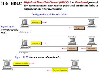
Layer 2 Framing HDLC (High-level Data Linl Control). HDLC. Typical Layer 2 protocol Services : Framing Error detection and frame retransmission Flow control Most of current line-based L2 protocols are derived from HDLC PPP (dial-up, ADSL, …) LAP-D (ISDN) LAP-B (X.25) ….

E N D
Layer 2 Framing HDLC (High-level Data Linl Control)
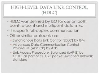
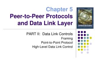
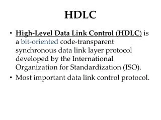
HDLC • TypicalLayer 2 protocol • Services: • Framing • Error detection and frame retransmission • Flow control • Mostofcurrentline-based L2 protocols are derivedfrom HDLC • PPP (dial-up, ADSL, …) • LAP-D (ISDN) • LAP-B (X.25) • …
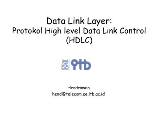
received frames transmitted frames Framing 0111110101 0110110111 Whyframing? FRAMES = “structured” information & control fields PHY = bit/byte streams PHY: - bit oriented 1000101010111010101010111 - byte oriented 10001000-01011000-11110110
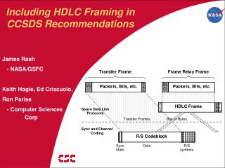
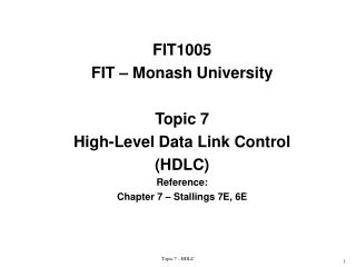
HDLC Frame Format • Each frame starts & ends with reserved flag: • 0111.1110 = 0x7e • Just one flag required between consecutive frames • Two consecutive flags = empty frame • Just ignore Flag 1 byte Address 1-n bytes Control 1-2 bytes Information (variable) FCS 2-4 bytes Flag 1 byte flag HDLC frame flag HDLC frame flag HDLC frame flag flag HDLC frame
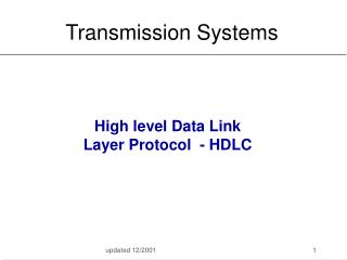
The needfor “stuffing” Flag 0111.1110 FRAME 0100.0100..0000.0000..0111.1000..0111.1110..0101.1110..0100.0000 Flag 0111.1110 0111.1110..0100.0100..0000.0000..0111.1000..0111.1110..0101.1110..0100.0000..0111.1110 Flag 0111.1110 FRAME 0100.0100..0000.0000..0111.1000 Flag 0111.1110 FRAME 0101.1110..0100.0000 Flag 0111.1110
Bit stuffing • HDLC Frame delineated by flag character • 01111110 • Six consecutive 1s • Bit stuffing: prevent occurrence of more than five 1s! • Transmitter inserts extra 0 after each consecutive five 1s inside the frame • Receiver checks for five consecutive 1s • if next bit = 0, it is removed • if next two bits are 10, then flag is detected • If next two bits are 11, then frame has errors
Bit stuffingexample EXAMPLE: send 0110111111111100 Data to be sent: 0111111001101111101111100001111110 After stuffing and framing EXAMPLE: receive 01111110000111011111011111011001111110 Data received After destuffing and deframing *000111011111-11111-110*
Byte stuffing • Byte-oriented channels? • Same stiffing idea, but stuffing via control escape octes: • Send (“reserved” byte) as (control escape octet) + (reserved byte)XOR(0010.0000) • Extra XOR (bit 5 complemented) for improved robustness • Control escape octet • 0111.1101 = 0x7d – of course NOW this is a reserved byte, too! Receiver detects control escape And removes it restoring original byte as part of the frame (e.g. not as flag) 11 3F 7E 02 7D 10 11 3F 7D 5E 02 7D 5D 10 See RFC 1662 for bit-stuffing over bit synchronous links (versus byte-oriented links)
HDLC Frame Content • Address: • Receiving (secondary) station • Or Transmitting (secondary) station in case ofresponse • 1111.1111 = broadcast address • Control • Frame type and transmissioncontrol information • FCS • CRC16 or CRC32 forerror detection • Sizeoffieldsdecidedduring link set-up/initialization procedure Flag 1 byte Address 1-n bytes Control 1-2 bytes Information (variable) FCS 2-4 bytes Flag 1 byte
Controlfield • Three types of frames • I = Information frame • S = Supervisory frame • U = Unnumbered frame 0 1 0 1 1
Information Frame • N(S) • # ofcurrentlytransmitted frame • N(R) • # ofnext frame expectedtobereceived • i.e., ACK ofallframesuntil N(R)-1 • P/F bit • For polling operation 0 N(S) P/F N(R) 8 bit case 0 N(S) P/F N(R) 16 bit case
Supervisory Frame 1 0 S P/F N(R) 8 bit case • Control frame usedtomanage ACK and flow control • S=RR (ReceiveReady) • Carries cumulative ACK up to N(R)-1 • S=RNR (ReceiveNotReady) • Blockssender (flow control), carries cumulative ACK aswell • S=REJ (Reject) • Negative ACK for frame # N(R), forGo-Back-N case • S=SREJ (SelectiveReject) • Negative ACK for frame # N(R), forSel. Repeat case • Extension: OTHER frame # toberetransmittedmaybeincluded in the frame information field 1 0 S 0 0 0 0 P/F N(R) 16 bit case
Unnumbered Frame 1 1 M P/F M • Framesusedfordatalink management • Initialization, Setup/release, Reset, Management and notificationofmalfunctions and issues • Severalcontrolmessages • Seedetails and examples in book • Differentdatalinkscenarios • AsynchronousBalanced Mode (ABM) LAP-B • Two full-duplex stations • NormalResponse Mode (NRM) • Unbalanced (half-duplex) operation: primary station can onlyaccess link, secondary station is slave • AsynchronousResponse Mode (ARM) • Like NRM, butsecondary station mayfurtherinitiateanunsolicitedtransmission