Download
1 / 31
310 likes | 449 Views
Project: IEEE P802.15 Working Group for Wireless Personal Area Networks (WPANs) Submission Title: [ PTC System Background and History - A Systems Overview ] Date Submitted: [ 2 May 2012 ] Source: [ Ken Jackson ] Company [ Rail Safety Consulting, A Division of TUV Rheinland ]

E N D
Project: IEEE P802.15 Working Group for Wireless Personal Area Networks (WPANs) Submission Title:[PTC System Background and History - A Systems Overview] Date Submitted: [2 May 2012] Source:[Ken Jackson] Company [Rail Safety Consulting, A Division of TUV Rheinland] Address [1151 Pittsford-Victor Rd, Pittsford, NY 14534, USA] Voice:[+1 585.203.1099], FAX: [+1 585.203.1094], E-Mail:[kjackson@railsafetyconsulting.com] Re: [If this is a proposed revision, cite the original document.] [If this is a response to a Call for Contributions, cite the name and date of the Call for Contributions to which this document responds, as well as the relevant item number in the Call for Contributions.] [Note: Contributions that are not responsive to this section of the template, and contributions which do not address the topic under which they are submitted, may be refused or consigned to the “General Contributions” area.] Abstract:[A presentation of the significant PTC systems developed since 1980] Purpose: [Intention of this document is to provide some comparative data and historical perspective on the various PTC systems created by partnerships between vendors and sponsoring railroads. It also explains some of the key radio features of the various systems.] Notice: This document has been prepared to assist the IEEE P802.15. It is offered as a basis for discussion and is not binding on the contributing individual(s) or organization(s). The material in this document is subject to change in form and content after further study. The contributor(s) reserve(s) the right to add, amend or withdraw material contained herein. Release: The contributor acknowledges and accepts that this contribution becomes the property of IEEE and may be made publicly available by P802.15. Ken Jackson, Rail Safety Consulting
PTC System Background & HistoryA Systems Overview Ken Jackson Rail Safety Consulting May 2, 2012 Ken Jackson, Rail Safety Consulting
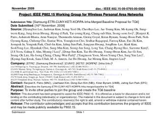
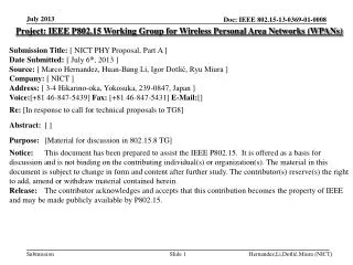
TIMELINE - RADIO BASED SYSTEMS Ken Jackson, Rail Safety Consulting
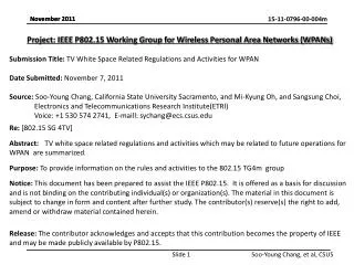
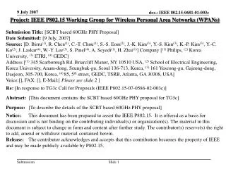
Generic PTC System Ken Jackson, Rail Safety Consulting
Replaced pole-to-pole wiring along railroad between signal locations. • Non-vital supervisory data link (R/Link by Safetran as example) • FSK/FM at 160 MHZ, UHF, or 900 MHz. • Transmitted code system control messages and indication messages via RF carrier between office and field location (wayside). • Operated from 300 baud to 4800 baud • Vital data was carried in coded AF track circuits. • Later versions (HD/Link by Safetran) used ATCS-200 messaging protocol to send vital data between field locations by radio. HD/Link radio was spread-spectrum low power. • Also used to relay AEI data and wayside detector data to signal locations. Before PTC - Radio Code Line Ken Jackson, Rail Safety Consulting
Joint development by railroads (AAR + Canadian), and several suppliers • Pre-GPS system • Was a standards building activity intended to drive future signal product development. • Used RF comms for “CTC code line”, “vital wayside-wayside”, ”vital wayside-train” messaging. • Strong interest and support in Canada – still being referenced in the Transport Canada archives. • Radio Messaging/protocol - ATCS-200 series standards are surviving artifacts used in other systems. Historic System - ATCSAutomated Train Control System Ken Jackson, Rail Safety Consulting
SPONSOR: AAR and Canadian Railroads, Transport Canada SUPPLIER(s): Safetran, others STRUCTURE: ISO 7 Layer, Synchronous HDLC-LAPB MESSAGING STD: ATCS 200 (series of stds) MAX BIT RATE: 4800 bps FREQ BAND: UHF, 900 MHz duplex (896 mobile TX, 935 base TX, 6 channels reserved for ATCS) MODULATION: FSK Baseband/Direct FM RADIO MFGR(s): Safetran, Harris, others. COMMS RANGE: LOS COMMS BETWEEN: base site, wayside, vehicle, STATUS: ATCS standard for vital and non-vital messaging over radio still in use. Historic System - ATCS Ken Jackson, Rail Safety Consulting
First system to use GPS for train location • Derived from Boeing 757/767 avionics system. • Intended to protect freight and passenger trains from mishaps • Demonstrated on 250 miles in Minnesota. Cost, management, and crew issues stopped it. Historic System - ARESAdvanced Railroad Electronics System Ken Jackson, Rail Safety Consulting
SPONSOR: BN/AMTRAK SUPPLIER(s): Rockwell Collins Demo 1985-1993 STRUCTURE: Proprietary MESSAGING STD: UNK - proprietary ? MAX BIT RATE: 2400 FREQ BAND: MICROWAVE (Pt-to-Pt), VHF 160 MHz RADIO MFGR: AAR Standard Radios (GE, Motorola, Harris, etc.) DISTANCE RANGE: Line of Signt COMMS BETWEEN: Base Wayside Locomotive STATUS: ARES shut down in 1993 in Minnesota Historic System - ARES Ken Jackson, Rail Safety Consulting
Followed ARES for BN (BNSF), added UP as a partner • Part of large scale GE-Harris development of optimized train movement mgmt. system • Collision prevention # 1 goal • Used Differential GPS for location • Radio portion: satellite two-way communication • Demonstrated on Oregon/Washington (Portland area) mainlines - 800 miles planned per news articles Historic System - PTSPositive Train Separation Ken Jackson, Rail Safety Consulting
SPONSOR: BNSF/UP/GE Harris SUPPLIER(s): GE-Harris, ROCKWELL and AMCI STRUCTURE: MESSAGING STD: MAX BIT RATE: FREQ BAND: UHF/VHF RADIO MFGR: Rockwell ?? COMMS RANGE: LOS COMMS BETWEEN: Wayside and train STATUS: Demonstration discontinued in Oregon/ Washington in 2000. Historic System - PTS Ken Jackson, Rail Safety Consulting
Planned to replace long-troubled BART track circuit based designs in a “standalone” manner. Several “kludges” for train separation would be replaced. • Applied first to original BART territory. • Derived from military vehicle location and comms system by Hughes Aircraft later acquired by Raytheon. • RF comms provided location by triangulation plus high speed data comms with trains. • Turned over to Harmon when Raytheon realized they couldn’t commercialize. • Many technical issues with translating from surface to subway application. • Development halted by GE after takeover of Harmon and subsequent customer issues. Historic System - BART AATCAdvanced Automated Train Control Ken Jackson, Rail Safety Consulting
SYSTEM: Advanced Automatic Train Control (BART) SUPPLIER(s): Raytheon then Harmon then GE STRUCTURE: ISO 7 layer MESSAGING STD: Military EPLRS MAX BIT RATE: Very high FREQ BAND: UHF – military 420 MHz proposed RADIO MFGR: Raytheon (for demonstrations) COMMS RANGE: Short range multiple TX/RX for location and data xmission COMMS BETWEEN: Among multiple waysides and to trains at all times STATUS: Contract cancelled / project abandoned by GE after Harmon acquisition. Historic System - BART AATC Ken Jackson, Rail Safety Consulting
Historic System - NAJPTC (IDOT PTC)North American Joint Positive Train Control - Illinois DOT • Also known as North American Joint PTC (NAJPTC) demonstration. • Started in 1995 with Southern Pacific, ARINC and CANAC using ATCS design. • Led by FRA, contracted to TTCI as client systems engineer and LMCo as supplier. • Wayside centric system – train profiles sent from “zone controller ” computer server, onboard database limited in scope. Digital distribution of bulletins and authorities planned. • Onboard equip subcontracted to Wabtec. • Operate standalone on prior dark territory (virtual signaling) and as overlay on CTC. • Intended to demonstrate vital operation with high speed passenger & freight. • Advanced crossing activation and quad gates – some crossing eliminations all to support 110 mph passenger operations. • Host railroad was UP with Amtrak participation. Ken Jackson, Rail Safety Consulting
Historic System - NAJPTC (IDOT PTC) • SPONSOR: IDOT/FRA/UP/AMTRAK/TTCI/AAR • SUPPLIER(s): Lockheed Martin with Wabtec Onboard • STRUCTURE: ISO 7 Layer, Synchronous HDLC-LAPB • MESSAGING STD: ATCS 200 • MAX BIT RATE: 9600 Bits/sec • FREQ BAND: VHF • RADIO MFGR: • DISTANCE RANGE: LOS • COMMS BETWEEN: Train to Wayside Zone Controller Ken Jackson, Rail Safety Consulting
System development contracted by BNSF to Wabtec • Work started in late 1990s after PTS and ARES • Non-vital overlay with continuous in-cab display • Deployed in several territories with different operating methods. • BNSF continues to expand and refine ETMS, I-ETMS is a spin off. • Uses MeteorComm radio Historic System - EMTS (I - VII)Electronic Train Management System Ken Jackson, Rail Safety Consulting
SPONSOR: BNSF SUPPLIER(s): Wabtec STRUCTURE: MESSAGING STD: MeteorComm proprietary MAX BIT RATE: FREQ BAND: 900 MHz being converted to 220 MHz RADIO MFGR: MeteorComm COMMS RANGE: LOS COMMS BETWEEN: Wayside and Locomotive & Office and Locomotive STATUS: In service on several different territories, being expanded per RSIA 08 Historic System - EMTS (I - VII) Ken Jackson, Rail Safety Consulting
Historic System - CBTMCommunications Based Train Management • Non-vital overlay PTC system from Wabtec • First application specific to “dark” territory, signaled operation to come later • Only goal to advise crew of need to stop/slow and enforce if no action taken. • In-cab display activated only when warning or alert needed for crew use, else blank. • Was demonstrated over 50 mile coal line territory • Intended to integrate with “NGD - New Generation Dispatch” at CSX HQ. Ken Jackson, Rail Safety Consulting
Historic System - CBTM • SPONSOR: CSX • SUPPLIER(s): Wabtec • STRUCTURE: Same as ETMS • MESSAGING STD: ATCS 200 • MAX BIT RATE: • FREQ BAND: • RADIO MFGR: MeteorComm • COMMS RANGE: LOS • COMMS BETWEEN: Wayside and Locomotive & Office and Locomotive • STATUS: Demonstration terminated - Superseded by I-ETMS and RSIA 08 Ken Jackson, Rail Safety Consulting
Overlay for New Jersey Transit • Merges two systems--continuous cab signaling and positive train stop (PTS) by intermittent cab linked to xponders. • The intermittent cab signal portion of the • Brings a train to a stop if it should run through a red signal, even if the train is traveling at less than 20 m.p.h. • Uses transponders to transmit speed enforcement data to train in each block. • Similar to ACSES except in-cab speed display was more sophisticated. • Had some technical issues when deployed – Ansaldo Sweden cab signal. Historic System - ASESAdvanced Speed Enforcement System Ken Jackson, Rail Safety Consulting
SPONSOR: NJ Transit SUPPLIER(s): US&S - Ansaldo STRUCTURE: MESSAGING STD: Eurobalise MAX BIT RATE: FREQ BAND: 27 MHz RADIO MFGR: Ansaldo COMMS RANGE: 6 feet COMMS BETWEEN: Transponders and Train STATUS: Not in use, to be superseded by ACES II (PTC system = ACSES II) Historic System - ASES Ken Jackson, Rail Safety Consulting
Began with Conrail/MDOT/AMTRAK to speed up passenger trains across Mich. • Initial development in mid 1990’s – still being upgraded to original 110 mph target • Includes advanced crossing start for high speed trains. • Was Harmon system based on VHLC and UltraCab Cab Signal designs. • Uses distributed “zones” of control which communicate peer-to-peer with vital data Historic/Current System - ITCSIncremental Train Control System Ken Jackson, Rail Safety Consulting
SPONSOR: GE/MDOT/AMTRAK/FRA (CONRAIL - NS) SUPPLIER(s): Harmon then GETS-GS STRUCTURE: OSI 7-layer GE proprietary layers 2, 3, 5, 7 TCP/IP and TDMA MESSAGING STD: Proprietary application over IP MAX BIT RATE: FREQ BAND: 220 MHz RADIO MFGR: GE MDS spread spectrum radio COMMS RANGE: Dependent on Wayside Zone design and train speed limits COMMS BETWEEN: Wayside zone and locomotive, Wayside-wayside (proprietary msg) STATUS: In service – being expanded, currently approved for 110 mph operation Historic/Current System - ITCS Ken Jackson, Rail Safety Consulting
System being used by all 7 class I RRs for FRA required PTC • Current plan is for about 60,000 miles to be equipped. • Also being used by commuter lines Metrolink, San Diego North County, likely to be used on TRE (DART) and others. • Vital onboard and wayside designs. • Primary vital communication is between Onboard & Wayside. • Radio is specific design ordered by the RRs (BNSF, UP, CSX, NS) who own the vendor. Current System - I-ETMSInteroperable Electronic Train Management System Ken Jackson, Rail Safety Consulting
SPONSOR: AAR/ITC Class I RRs SUPPLIER(s): Wabtec, MeteorComm, plus other suppliers for Wayside logic STRUCTURE: Proprietary “ITCNet”, OSI 7 layer TCP/IP MESSAGING STD: ITC AAR Standard, Class D messages, Edge Message Protocol (EMP) MAX BIT RATE: per radio (TCP/IP 10 Mbps) FREQ BAND: 220 MHz RADIO MFGR: MeteorComm COMMS RANGE: LOS COMMS BETWEEN: Wayside and Vehicle Office and Vehicle STATUS: Under test in several RR laboratories, field tests starting in 2012. Current System - I-ETMS Ken Jackson, Rail Safety Consulting
Track circuit/cab signal overlay required by FRA for High Speed 150 mph AMTRAK operation on NEC (Acela trains) • Originally conceived by AMTRAK (Larry Light) • Used exclusively on NEC for AMTRAK • Original version does not have TSR radio transmission – portable programmable xponders used instead – being superseded by ACSES II with TSR radio. Current System - ACSES IIAdvanced Civil Speed Enforcement System Ken Jackson, Rail Safety Consulting
RADIO FOR TRANSMITTING SIGNAL ASPECT AND TSRs SPONSOR: AMTRAK SUPPLIER(s): Alstom/PHW STRUCTURE: ACSES II CDMA/TDMA standard MESSAGING STD:ATCS 200 MAX BIT RATE: approx 9600 bps FREQ BAND: 900 MHz ATCS Channels, being converted to 220 MHz at 12.5 kHz channel spacing. RADIO MFGR: GE MDS COMMS RANGE: LOS with controlled power output COMMS BETWEEN: Wayside base station and train STATUS: In service - Northeast Corridor Current System - ACSES IIAdvanced Civil Speed Enforcement System Ken Jackson, Rail Safety Consulting
TRANSPONDERS SPONSOR : AMTRAK SUPPLIER(s): Alstom/Ansaldo STRUCTURE: Eurobalise - short distance MESSAGING STD: Eurobalise, 170 bits data, 72 bits CRC, 255 total bits MAX BIT RATE: 50 KBPS FREQ BAND: 27 MHz carrier energize, 4.5 MHz response FSK message RADIO MFGR: Alstom Europe/ Ansaldo Europe DISTANCE RANGE: about 10 feet COMMS BETWEEN: track mounted xponder and locomotive or MU Car STATUS: In service – Northeast Corridor Current System - ACSES II Ken Jackson, Rail Safety Consulting
True Moving block CBTC with local zone control • Radio system is a (proprietary) high-speed vital local area network between train & zone controller and between zone controllers • Zone Controllers use fiber based physical network to other zone controllers • Both above ground and subway tunnel operation. • Uses Transponders for train location with tachometer type incremental navigation Current System - NYCT CBTCCommunication Based Train Control Ken Jackson, Rail Safety Consulting
SPONSOR: New York City Transit (PATH) • SUPPLIER(s): Siemens + Thales • STRUCTURE: IP Messaging Scheme – proprietary application • MESSAGING STD:WLAN Siemens std. • MAX BIT RATE: 128 KBPS per train (4 MBPS total max) • FREQ BAND: 5.725Ghz - 5.825Ghz • RADIO MFGR: Siemens Type PULZ80 • COMMS RANGE: limited • COMMS BETWEEN: Wayside zone controllers and Trains and other zone controllers • STATUS: Operating on NYCT Canarsie Line, being installed on PATH, NYCT Flushing Line and Culver Line Test Track. Current System - NYCT CBTC Ken Jackson, Rail Safety Consulting
ENDAdditions and ImprovementsWelcome ! Ken Jackson, Rail Safety Consulting