Download
1 / 25
270 likes | 462 Views
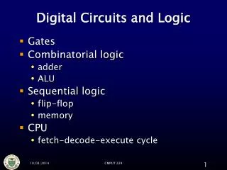
LOGIC DESIGN AND CIRCUITS. BASIC LOGIC GATES Res . Assist . Hale İNAN. CONTENT. Sample 14-bit I Cs 74LS08 IC (AND) 74LS32 IC (OR) 74LS04 IC (NOT) 74LS00 IC (NAND) 74LS02 IC (NOR) 74LS86 IC (XOR) Breadboard Connection Steps. AND Gate (74LS08 IC).

E N D
LOGIC DESIGN AND CIRCUITS BASIC LOGIC GATES Res. Assist. Hale İNAN
CONTENT • Sample 14-bit ICs • 74LS08 IC (AND) • 74LS32 IC (OR) • 74LS04 IC (NOT) • 74LS00 IC (NAND) • 74LS02 IC (NOR) • 74LS86 IC (XOR) • Breadboard Connection Steps
AND Gate (74LS08 IC) • Figure on the left represents 74LS08 IC. • This device contains 4 independent and gateseach of whichperformsthelogicANDfunction. • Ifboth A and B aretrue, then Q is true.
OR Gate (74LS32 IC) • Figure on the left represents 74LS32 IC. • This device containsfourindependentgateseach of whichperformsthelogicORfunction. • If either A or B is true, then Q is true.
NOT Gate (74LS04 IC) • Figure on theleftrepresents 74LS04 IC. • This device contains six independent gates each of which performs the logic INVERT function. • If A is not true, then Q is true.
NAND Gate (74LS00 IC) • Figure on theleftrepresents 74LS00 IC. • This device contains four independent gates each of which performs the logic NAND function. • If either A or B are not true, then Q is true.
NOR Gate (74LS02 IC) • Figure on the left represents 74LS02 IC. • This device contains four independent gates each of which performs the logic NOR function. • If both A and B are not true, then Q is true. • Note that the pin configuration for the two integrated circuits is different. (NOR & AND)
XOR Gate (74LS86 IC) • Figure on the left represents 74LS86 IC. • This device contains four independent gates each of which performs the logic XOR function.
SWITCH • A switch is a component which controls the open-ness or closed-ness of an electric circuit. • Open / Closed • OFF state: Open-circuit (preventing current from flowing) • ON state: Closed-circuit(allowing current to flow)
Breadboard Connections – Step 1 • The red wire represents positive pin and black one represents negative pin.