Download
1 / 25
250 likes | 364 Views
INVESTIGATION OF THIN FILMS AND CLUSTERS BY SCANNING PROBE TECHNIQUES. Natascha Niermann, concerning the phd progamm FB Physik, Surface Physics Universität Osnabrück, 49069 Osnabrück. content. problem: informations of materials description of used analysis methods

E N D
INVESTIGATION OF THIN FILMS AND CLUSTERS BY SCANNING PROBE TECHNIQUES Natascha Niermann, concerning the phd progamm FB Physik, Surface Physics Universität Osnabrück, 49069 Osnabrück
content • problem: informations of materials • description of used analysis methods • some results and the problems I had so far within the tests and tries • ideas how to improve the techniques? • future plans regarding different materials to investigate and different possibilities of type of exploring • summary and outlook
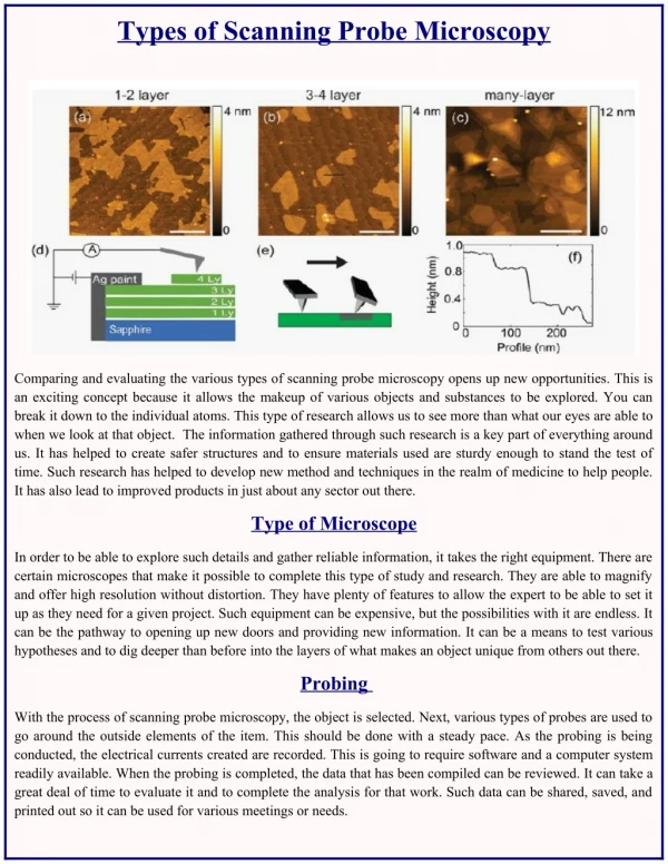
types of scanning probe microsopy • origin of all scanning probe techniques is the > scanning tunneling microscopy, invented by Binning and Rohrer in the 80‘s • from this time on there have been developed a number of variations or further developments • in my work used techniques now are AFM(atomic force microscopy) and MFM(magnetic force microscopy) and spin polarized STM
scanning tunneling microscopy etched tip e.g. of tungsten is used to scan the surface, piezo allows small movements • STM uses quantum mechanical tunneling effect of electron waves between two electrodes • a tunneling current that can be measured bringing a tip close to the surface, no need for contact, gap ~ 10 Å
scanning force microscopy • AFM in air or in a liquid cell: • contact mode, topography, normal forceand lateral force • dynamicmode (intermittent contact mode or Tapping mode™), topography, phase shift, amplitude • AFM in UHV: • contact mode, topography, normal forceand lateral force • - dynamic mode (non contact mode), topography, damping,frequency shift Nanoscope Multimode 3 STM/AFM/MFM
Einfallender Laserstrahl Fotodiode Reflektierter Laserstrahl Cantilever Spitze Probe auf dem Scanner Atomic force microscopy > light detector system Schwingquartz • function of the four quadrant photodiode: • the normal force FN respectively the frequency is detected vertically • the lateral force FL is detected horizontally • Static mode • the distance is regulated by a fixed force (setpoint FN) > • you acquire an equiforce plane • Dynamic mode • an oscillating quartz drives the cantilever • the cantilever oscillates with the resonance frequency • with decreasing distance the resonance frequency decreases • the distance is regulated according to a fixed shift of the frequency • a plane of constant frequency shift (force gradient) is measured
AFM/MFM – amplitude regulation • principle of the dynamic mode in UHV (FM-MODE) • Cantilever working Eigenfrequecy • Excitation frequency nearby resonance frequency • Oscillation frequency depends on force gradient • amplification by loop gain to keep constant amplitude
distance regulation AFM/MFM • Excitation frequency by mixing frequency measured at photodetector with reference frequency • resonance frequency of the cantilever between 10 and 500 kHz • frequency shift by force gradient of the sample is used for controlling the distance • the shift is held constant through the correction of distance between sample and cantilever
first results • STM topography of tempo molecules on a clean gold surface in air, tempo solved at 2x10⁻⁴ in ethanol
overview of used samples • we have used two different types of amorphous gold surfaces as substrate exhibiting flat (111) terraces <1nm • molecules with different properties and sizes, like TEMPO • single crystal surfaces with magnetic metallic sub-mono-layers Structure Of TEMPO stolen from Prof. Walder
untreated amorphous goldsurface • quasi 3D view 1 nm2 of amorphous gold, surface oxidated
amorphous gold: flash annealed 5 µm • corrugation of the gold surface after „flashing“: • height differences about 50 nm • cell-type structure of the flat terraces • deep valleys inbetween of up to 10 nm 5 µm
preparation of SAMs on surfaces SAM( > means self assembling monolayer) : -preparation of the substrate itself ( e.g. cleaning or hydroxylisation ) solution for coating: -making a solution with OTS, thiols or tempo with a appropriate solvent -coating eventually in a clean,e.g. nitrogen, environment Typical parameters of preparation:concentration of water in the solvent, age of the solution, temperature, type of annealing process substrate, chain length and concentration Methods of investigation: STM,AFM,MFM, Ellipsometry, test of chemical properties (e.g. pH)
thiols on gold • image taken with a Nanoscope • gold surface with monolayer of thiols • in holes in the layer the thickness of the layer could be measured (ca. 2nm)
OTS islands on gold • OTS (C18H37Cl3Si) sub monolayer, height of the layer with 1,8nm • on SiOx comparable height but different types of islands
UHV deposited gold • view of a gold terrace made by MBE at about 10-7 mbar pressure, • 2nm height differences
TEMPO on gold • overview of different structures directly • three types of structuring
first ideas about structure • aggregate directly upon deposition of molecules
After a while: more order • period of the pattern is 1 nm • matches with theoretical sizes
after filtering • correlation filtering • code by Bas Hulsken from Nijmegen
submomolayers of magnetic materials • comparison between cobalt clusters on the left and iron clusters on silver(100) on the right (STM-measurement)
submonolayer cobalt on silver(100) 5-15 Angström: diameter of the clusters, 1-2 atomic layers
topographic and magnetic information corrugation 4nm Scan of 500 x 500 micrometer this example shows a comparison betweeen corrugation and magnetic structure information detected with an MFM cantilever, distance for the measurement varies, identical position
troubleshooting • UHV at about 1x10⁻¹⁰ mbar • leaks (most annoying) • repair or upgrade means breaking the vacuum ... Afterwards bake out necessary
Plans for the future • uncovering the structure of theTEMPO layer, • characterization of the binding • magnetic properties (investigation with MFM and spin polarized STM) in cooperation with Prof Jaitner • structure and the magnetic properties of vanadium on silver as a comparison to cobalt and iron • VT AFM/STM