Download
1 / 26
270 likes | 430 Views
I-7 Electric Energy Storage. Dielectrics. Main Topics. Electric Energy Storage . Inserting a Conductor into a Capacitor. Inserting a Dielectric into a Capacitor. Microscopic Description of Dielectrics Concluding Remarks to Electrostatics. Electric Energy Storage I.

E N D
Main Topics • Electric Energy Storage. • Inserting a Conductor into a Capacitor. • Inserting a Dielectric into a Capacitor. • Microscopic Description of Dielectrics • Concluding Remarks to Electrostatics.
Electric Energy Storage I • We have to do work to charge a capacitor. • This work is stored as a potential energy and all (if neglecting the losses) can be used at later time (e.g. faster to gain power). • If we do any changes to a charged capacitor we do or the field does work. It has to be distinguished whether the power source is connected or not during the change.
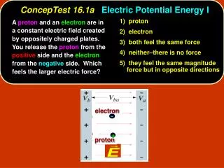
Electric Energy Storage II • Charging a capacitor means to take a positive charge from the negative electrode and move it to the positive electrode or to take a negative charge from the positive electrode and move it to the negative electrode. • In both cases (we can take any path) we are doing work against the field and thereby increasing its potential energy. Charge should not physically pass through the gap between the electrodes of the capacitor!
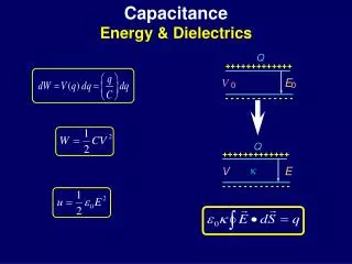
Electric Energy Storage III • A capacitor with the capacitance C charged by the charge Q or to the voltage V has the energy: Up = Q2/2C = CV2/2 = QV/2 • The factor ½ in the formulas reveals higher complexity then one might expect. By moving a charge between the electrodes we also change Q, V so we must integrate.
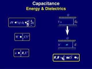
Electric Energy Storage IV • The energy density • Let us have a parallelplate capacitor A,d,C, charged to some voltage V: • Since Ad is volume of the capacitor we can treat 0E2/2 as the density of (potential) energy • In uniform field each volume contains the same energy.
Electric Energy Storage V • In non-uniform fields energy has to be integrated over volume elements where E is (approximately) constant. • In the case of charged sphere these volumes would be concentric spherical shells ( r > ri) :
Electric Energy Storage VI • Integrating from some R rito infinity we get : • For R = ri we get the same energy as from a formula for spherical “capacitor”. • We can also see, for instance, that half of the total energy is in the interval ri < r < 2ri or 99% of the total energy would be in the interval ri < r < 99ri
Inserting a Conductor Into a Capacitor I • Let us insert a conductive slab of area A and thickness < d into the gap between the plates of a parallel plate capacitor A,d, 0,. • The conductive slab contains enough free charge to form on its edges a charge density p equal to the original . So the original field is exactly compensated in the slab. • Effectively the gap changed to d - .
A Guiz • Inserting a conductive slab of area A and thickness < d into the gap between the plates of a parallel plate capacitor A,d, 0, will increase its capacitance. • Where should we put the slab to maximize the capacitance ? • A) next to one of the plates. • B) to the plane of symmetry. • C) it doesn’t matter.
C: It doesn’t matter ! • Let us insert the slab some distance x from the left plate. Then we effectively have a serial connection of twocapacitors, both with the same A. One has the gap x and the other d-x-. So we have:
Inserting a Conductor Into a Capacitor II • The capacitance has increased. • In the case of disconnected power source the charge is conserved and the energy decreases – the slab would be pulled in. • In the case of connected power source the voltage is conserved and the energy increases – we do work to push the slab in and also the source does work to put some more charge in.
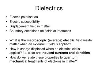
Inserting a Dielectric Into a Capacitor I • Let us charge a capacitor, disconnect it from the power source and measure the voltage across it. When we insert a dielectric slab we shall notice that • The voltage has dropped by a ratio K = V0/V • The slab was pulled in by the field • We call K the dielectric constant or the relative permitivity (r) of the dielectric. • rdepends on various qualities T, f!
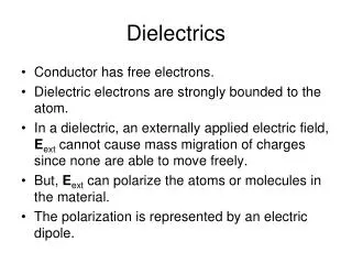
Inserting a Dielectric Into a Capacitor II • What has happened : Since the inserted plate is a dielectric it contains no free charges to form a charge density on its edges, which would be sufficient to compensate the original field. • But the field orientates electric dipoles. That effectively leads to induced surface charge densities which weaken the original field and thereby increase the capacitance.
Inserting a Dielectric Into a Capacitor III • The field orientates electric dipoles their charges compensate everywhere except on the edges next to the capacitor plates, where some charge density p < remains. • The field in the dielectric is then a superposition of the field generated by the original and the inducedp charge densities. • In the case of homogeneous polarization the induced charge density p = P which is so called polarization orthe density of dipole moments.
Inserting a Dielectric Into a Capacitor IV • Inserting dielectrics is actually the mosteffective way to increase the capacitance. Since the electric fielddecreases, the absolute “breakdown” chargeincreases. • Moreover for most dielectrics their breakdownintensity (or dielectric strength) is higher than that of air. They are better insulators!
Energy Density in Dielectrics • If we define the permitivity of a material as: = K0 = r0 and use it in all formulas where 0 appears . For instance the energydensity can be written as E2/2. If dielectrics are non-linear or/and non-uniform their description is considerably more complicated!
Capacitor Partly Filled with a Dielectrics • If we neglect the effects near the edges of the dielectrics, we can treat the system as a serial or/and parallel combination of capacitors, depending on the particular situation.
Concluding Remarks To Electrostatics • We have illustrated most of things on very simplified examples. • Now we know relatively deeply all the important qualitative principles of the whole electrostatics. • This should help us to understand easier the following parts ad well as functioning of any device based on electrostatics!
Homework • The homework from yesterday is due tomorrow!
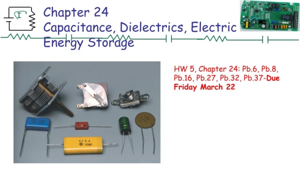
Things to Read • This lecture covers : • Chapter 24 – 4, 5, 6 • Advance reading : • Chapter 25 – 1, 2, 3, 5, 6
Charging a Capacitor • Let at some point of charging the capacitor C have some voltage V(q) which depends on the current charge q. To move a charge dq across V(q) we do work dEp = V(q)dq. So the total work to reach the charge Q is: ^
Polarization Dipole Moment Density I Let us take some volume V which is small in the macroscopic scale but large in the microscopic scale so it is representative of the whole sample:
Polarization Induced Surface Charge Density II Let a single dipole moment p = lq be confined in a prism of the volume v = al. A volume V of the uniformly polarized dielectric is built of the same prisms, so the polarization must be the same as in any of them:
Polarization III The result field in the dielectric : We can express the original charge density: So the original field is distributed to the result field and the polarization according to the ability of the dielectric to be polarized.
Polarization IV In linear dielectrics is proportional to the result field . They are related by the dielectric susceptibility : The result field E is K times weaker than the original field E0 and can also define the permitivity of a dielectric material as . ^