Download
1 / 20
200 likes | 301 Views
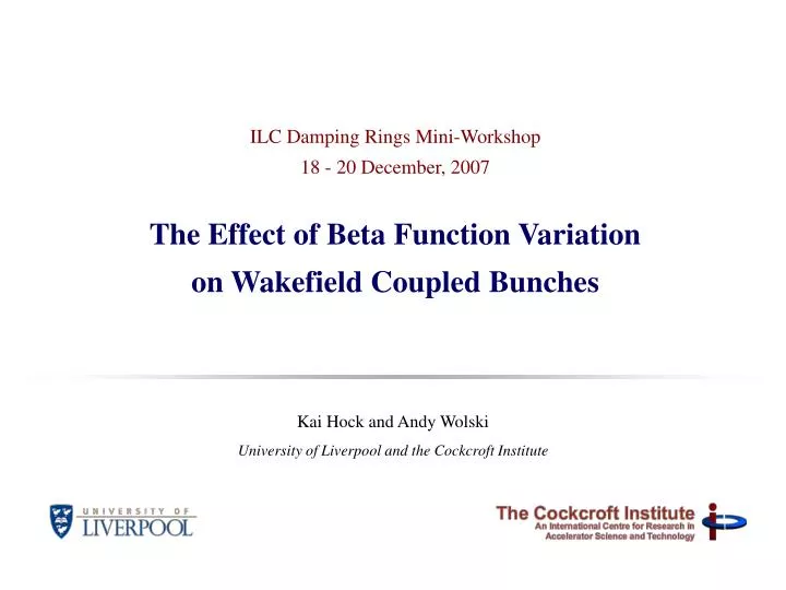
ILC Damping Rings Mini-Workshop 18 - 20 December, 2007 The Effect of Beta Function Variation on Wakefield Coupled Bunches. Kai Hock and Andy Wolski University of Liverpool and the Cockcroft Institute. Introduction.

E N D
ILC Damping Rings Mini-Workshop18 - 20 December, 2007The Effect of Beta Function Variation on Wakefield Coupled Bunches Kai Hock and Andy Wolski University of Liverpool and the Cockcroft Institute
Introduction • To study the transverse instability of bunches coupled by the resistive wall wakefield in the ILC damping ring. • Time domain simulation for OCS6 damping ring • . Standard model and analytical results • . Simulation method on real lattice • Unexpected behavior on the real lattice • . Deviations from model in a simple lattice • . Comparison with effect of HOM, uneven fill • Transient effects during injection and extraction • . Fill patterns, feedback system, emittance, NEG coating, … • . Convergence issues
The ILC damping rings baseline configuration RF shaft &cavern wiggler wiggler injection extraction shaft &cavern wiggler wiggler RF
Coupled bunch instabilities • Long-range wake fields in the damping rings are of concern for two reasons: • Initial estimates based on resistive-wall wake fields indicate coupled-bunch instability growth rates that could be challenging to deal with. • The large jitter of injected bunches could couple through the wake fields to damped bunches awaiting extraction, leading to bunch-to-bunch jitter in the extracted beam that exceeds specifications. • The stability of the beam extracted from the damping rings is critical for the performance of the ILC, so we are therefore taking a careful look at the effects of long-range wake fields. • Generally, time-domain simulations confirm the growth rates expected from analytical estimates… Initial growth rates from simulation using real beta function.
OCS6 Growth Rate Max. growth rate = 1.49 ms-1 Growth time = 670s or 30 turns 23% higher Electrons / bunch 21010 Al conductivity 3.21017 s-1 Beam pipe radius 2 cm Vertical tune 49.31 Bunch Number 3649
Transverse Resistive Wall Wakefield Coupled Bunches • Results so far • Including the realistic variation in the beta function results in higher growth rates even in a simple lattice, compared to analytic average beta function results. • Uneven fill pattern, HOM have relatively small effects in the OCS6 damping ring. • Ongoing • To simulate transient effects on extracted bunches, due to jitter of injected bunches.
Resistive wall wakefield F n+1 y z n c Force on bunch n: F ~ W1(-c)yn+1 Assume (Chao 1993)
n+1 n+3 n n+4 n+2 Standard model & analytic results z Assume constant beta function: Betatron oscillation Wakefield sum Obtain eigenmodes: (Fourier modes) Derive growth rates: (widely used)
Simulation Method • Should not integrate equation of motion directly as this is assumes constant beta function: • At each time step, add kick to momentum from wakefield. • Transform to action angle variables (J-), phase advance 1 step. • Transform back to Cartesian (x,px), add kick, repeat. kick kick (x,px) (J-) t (J-) (x,px) (x,px) (J-) kick The actual (varying) beta function is used in the phase advance.
Simple Lattice – 10 FODO Cells Variation in beta function causes coupling of multi-bunch modes. As a result … Max. growth rate is larger than analytic result for constant beta. Decay modes can grow. (a) (b) Figure 24. Amplitudes of (a) mode 2 and (b) mode 3 in the simple lattice with 4 bunches. The points are sampled for 1 turn at every 10 turns. (Hock, Wolski, Phys. Rev. ST Accel. Beams 10, 084401 (2007))
OCS6: Comparison of Effects on Growth Rates HOM, uneven fill can also produce mode coupling, but their effects are smaller than that of beta function variation in ILC damping ring Resistive wall Constant beta Figure 4. (Color) Simulation results for mode 100 using the actual, varying beta function of the ILC damping ring. The graph shows the amplitude of the normalized action constructed from the data.
Discrepancy due to varying beta • Assuming constant beta function, equations of motion can be decoupled after transforming to Fourier modes: • If beta function varies, equations cannot be decoupled. Attempting to do so results in mode coupling term: • Since Fourier modes are no longer eigenmodes, mode mixing can take place.
To illustrate … Decay modes grow because Fourier modes are no longer eigenmodes. Decay mode Decay mode Growth mode NB. All modes shown here are Fourier modes This also means that the analytic growth rate is no longer valid.
Ongoing Work – Transient Effects (ILC RDR Vol. 3, 2007, fig. 1.3-1) • injection transients emittance growth • finite wall wake function • NEG coating • feedback system requirements • wake sum convergence problem • groove chamber surface • OCS8
Injection Transients Emittance Growth • Continue studies to quantify the effects of injection transients. Simplify to reduce compute time Wake sum not yet converged (100 terms)
Feedback System • Provide information required for the specification and development of the fast feedback systems; • John Fox (SLAC) is the proposed work package manager for the bunch-by-bunch feedback systems. Required gain inversely related to growth time, (Wolski 2004) Performance limited by maximum achievable V Wake sum not yet converged (100 terms)
Wake Sum using FFT Convolution No. of terms needed to converge Computation time needed Addition of wakefield terms can be arranged into discrete convolution (Koschik 2004)
Finite Wall Wake Function • More sophisticated wake function models will be considered to improve accuracy of simulation and to include multilayer walls, e.g. NEG coating • Gluckstern (2000), Zotter (2005), Al-Khateeb (2007): • Matching of boundary conditions at interfaces • gives linear system of equations • Badly conditioned because coefficients span up to • 12 orders of magnitude • - Analytic solution necessary, e.g. Mathematica Al NEG
NEG Coating – Multi-layer Wake Function • Estimate the impact of NEG coating • Some work has already been done for other machines: e.g. R. Nagaoka, "Study of resistive-wall effects on Soleil," Proceedings of EPAC'04, Lucerne, Switzerland (2004).
Conclusion • 1. Analytic result of growth time from resistive wall wakefield is 36.7 turns. Feedback damping time achievable is smaller but of similar order of magnitude. • 2. Variation of beta function in real lattice reduces growth time to 30 turns. This could approach the limit of feedback system performance. • Wakefield of injected bunches induces vertical jitter in extracted bunches that may exceed 10% for 2 pm emittance. • Convergence problem in wakefield sum is solved using FFT convolution technique and will provide more accurate answers on transient effects. • More realistic effect of feedback control can now be calculated using time domain simulation.