Download
1 / 36
360 likes | 446 Views
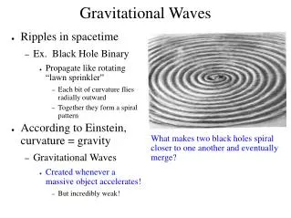
Measuring gravitational waves with GEO600. Martin Hewitson and the GEO team. Introduction. DRMI gives 2 output signals, each containing GW information – P(t) and Q(t) There is a transfer function from h(t) to P(t) and from h(t) to Q(t) Tp(f) = P(f) / h(f) and Tq(f) = Q(f)/h(f)

E N D
Measuring gravitational waves with GEO600 Martin Hewitson and the GEO team
Introduction • DRMI gives 2 output signals, each containing GW information – P(t) and Q(t) • There is a transfer function from h(t) to P(t) and from h(t) to Q(t) • Tp(f) = P(f) / h(f) and Tq(f) = Q(f)/h(f) • Each comprise an optical part and an electronic part • Each vary (slowly?) in time • We want to calibrate P(t) and Q(t) to h(t) on-line • Need to estimate Tp(f) and Tq(f) hp(t) and hq(t) • Combine hp(t) and hq(t) to get optimal h(t) GEO meeting Sept 2004
In the steady state…. GEO meeting Sept 2004
Transfer functions h(t)P,Q GEO meeting Sept 2004
Optical transfer function - equations • For each quadrature, P and Q, • Overall gain • Pole frequency • Pole Q • Zero frequency GEO meeting Sept 2004
Measured optical response - P GEO meeting Sept 2004
calibration Calibration overview GEO meeting Sept 2004
Calibration software tasks GEO meeting Sept 2004
On-line measurement of Tp(f) GEO meeting Sept 2004
Optimisation routine • Fit models of the transfer functions to the measured ones • 8 parameter fit • Gp, Ppf, Ppq, Pzf, Gq, Qpf, Qpq, Qzf • Electronic parameters are fixed • Algorithm uses various minimisation methods to find the best parameter set that describes the data • It also returns a measure of success – c2 GEO meeting Sept 2004
Undoing the effect of the optical response • The parameters from sys id can be used to generate inverse optical response • Poles to zeros, zeros to poles, invert gains • IIR filters are designed for these inverted responses • Overall gains are treated separately • Filters are applied to up-sampled error-point to give better filter response Inverse P GEO meeting Sept 2004
Generating loop-gain correction signals • A full set of IIR filters has be constructed to match the response of the feedback electronics in the detection band • One set for fast feedback, one set for slow feedback • Error-point signal is filtered through these electronics filters and then through actuator filters • This produces two ‘displacement’ signals that correct for the loop gain of the MI servo GEO meeting Sept 2004
Fast path (UG 100 Hz) electronics model GEO meeting Sept 2004
Slow path (UG 8 Hz) electronics model GEO meeting Sept 2004
Calibration pipeline – hp(t) GEO meeting Sept 2004
Parameter estimation results - P GEO meeting Sept 2004
Parameter estimation results - Q GEO meeting Sept 2004
c2 behaviour • The measure of success from the optimisation routine tells us something about data quality • c2 depends on SNR of calibration lines in P GEO meeting Sept 2004
Quality channel • One 16-bit sample per second • Encodes information from • Lock status • Maintenance status • c2 threshold crossings • So far, c2 thresholds have been chosen arbitrarily This will be extended soon – see data quality indicators talk 32 bit sample per sec GEO meeting Sept 2004
Measured c2 behaviour GEO meeting Sept 2004
Measured c2 behaviour GEO meeting Sept 2004
Measured c2 behaviour noise estimation (s2) GEO meeting Sept 2004
hp(f) and hq(f) – validation I GEO meeting Sept 2004
ESD calibration - Validation II Labbook pages 1587, 1596, 1602 GEO meeting Sept 2004
Combining hp(t) and hq(t) • With ‘correct’ hp(t) and hq(t) we can try to combine them to get some optimal h(t) • Both signals represent (apparent) strain • Each contain some differential arm-length change information (real strain) • So, far only tried a couple of simple examples • Simple mean • High/low pass filter combination GEO meeting Sept 2004
Simple mean combination h(t) = [hp(t) + hq(t)] / 2 GEO meeting Sept 2004
Simple mean combination – phase check GEO meeting Sept 2004
Filtered combination – highpass+lowpass h(t) = lowpass{hp(t)} + highpass{hq(t)} GEO meeting Sept 2004
Filtered combination – results h(t) = lowpass{hp(t)} + highpass{hq(t)} GEO meeting Sept 2004
Filtered combination – phase check GEO meeting Sept 2004
Current and future work • Q quadrature parameters are now successfully estimated and signal is calibrated to hq(t) • Updating of the optical filters needs more extensive studies to look for artefacts • More studies of c2 values for P+Q simulations • More studies of c2 values for P+Q ‘real’ data • How to combine h(t)_P and h(t)_Q ? • Some simple ideas already exist • Other possibilities should be explored • The combined h(t) needs studied for artefacts • Include more automation • MI loop gains read from LabVIEW • Add more data quality checks – extend quality channel bits • Try using recorded feedback signals for loop-gain correction GEO meeting Sept 2004
Pros and cons • Pros • Calibration is updated once per second • Accuracy to ~10% from 50Hz to 6kHz • Runs on-line with 2 min latency – time-domain • Produces calibrated time-series – hp(t), hq(t) • Cons • Fast (>1Hz) optical gain fluctuations ignored • Outwith valid frequency range, accuracy is poorer • Bottom line is ESD calibration – good to about 5% • Need independent check of ESD • Photon pressure calibrator GEO meeting Sept 2004
Intermission (Pause) GEO meeting Sept 2004
Introducing GEO Summary Pages • Track fixed measurements over lock stretches • Same set of measurements is performed on each data segment • Lock stretches can be overnight runs, weekend runs, science runs • A report is produced (web page) for each data segment • Quick-look way of comparing detector status over days • Also gives information about data quality • Q: Should this data segment be analysed? GEO meeting Sept 2004
GEO Summary Pages – calibration quality • GEO Summary pages focus primarily on calibration quality and sensitivity measures so far • Min/Max spectra • BLRMS sensitivity • Data quality channel – locked?, Maintenance? • Recovered parameters • c2 values • Lock lists and duty cycle • Will be extended to include GEO++ monitor outputs (see Ajith’s talk) GEO meeting Sept 2004
Where to look • Index of reports appears at http://www.geo600.uni-hannover.de/georeports/index.html • The list of reports is split into months • Each entry is a summary of the full report • Links take you to the full report Let’s have a look… GEO meeting Sept 2004