Download

1 / 45
450 likes | 658 Views
DMA & Interrupts. By Santhosh H. S. DMA. DMA Definitions: DMA occurs between an I/O device and memory without the use of the microprocessor DMA read transfer data from the memory to I/O device DMA write transfer data from the I/O to memory

E N D
DMA & Interrupts By Santhosh H. S
DMA • DMA Definitions: • DMA occurs between an I/O device and memory without the use of the microprocessor • DMA read transfer data from the memory to I/O device • DMA write transfer data from the I/O to memory • MRDC & IOWC signals to simultaneously activate for read DMA
Basic DMA operation • The direct memory access (DMA) I/O technique provides direct access to the memory while the microprocessor is temporarily disabled. • A DMA controller temporarily borrows the address bus, data bus, and control bus from the microprocessor and transfers the data bytes directly between an I/O port and a series of memory locations. • The DMA transfer is also used to do high-speed memory-to memory transfers. • Two control signals are used to request and acknowledge a DMA transfer in the microprocessor-based system.
The HOLD signal is a bus request signal which asks the microprocessor to release control of the buses after the current bus cycle. • The HLDA signal is a bus grant signal which indicates that the microprocessor has indeed released control of its buses by placing the buses at their high-impedance states. • The HOLD input has a higher priority than the INTR or NMI interrupt inputs.
The 8237 DMA controller • The 8237 DMA controller supplies the memory and I/O with control signals and memory address information during the DMA transfer. • The 8237 is capable of DMA transfers at rates of up to 1.6M bytes per second. • Each channel is capable of addressing a full 64K-byte section of memory and can transfer up to 64K bytes with a single programming.
DREQ3 – DREQ0 (DMA request): Used to request a DMA transfer for a particular DMA channel. • DACK3 – DACK0 (DMA channel acknowledge): Acknowledges a channel DMA request from a device. • HRQ (Hold request): Requests a DMA transfer. • HLDA (Hold acknowledge) signals the 8237 that the microprocessor has relinquished control of the address, data and control buses. Some important signal pins
MEMW (Memory write): Used as an output to cause memory to write data during a DMA write cycle. • MEMR (Memory read): Used as an output to cause memory to read data during a DMA read cycle • A3 – A0 : address pins select an internal register during programming and provide part of the DMA transfer address during DMA operation. • A7 – A4 : address pins are outputs that provide part of the DMA transfer address during a DMA operation. • DB0 – DB7 : data bus, connected to microprocessor and are used during the programming DMA controller.
Data Transfer modes • Single Transfer Mode • In Single Transfer mode the device is programmed to make one transfer only. • The word count will be decremented and the address decremented or incremented following each transfer. • When the word count ``rolls over'' from zero to FFFFH, a Terminal Count (TC) will cause an Auto initialize if the channel has been programmed to do so.
Block Transfer Mode • In Block Transfer mode the device is activated by DREQ to continue making transfers during the service until a TC, caused by word count going to FFFFH, or an external End of Process (EOP) is encountered. • DREQ need only be held active until DACK becomes active. Again, an Auto initialization will occur at the end of the service if the channel has been programmed for it.
Interrupts • Interrupt is a process where an external device can get the attention of the microprocessor. • The process starts from the I/O device • The process is asynchronous. • Classification of Interrupts • Interrupts can be classified into two types: • Maskable Interrupts(Can be delayed or Rejected) • Non-Maskable Interrupts (Can not be delayed or Rejected) • Interrupts can also be classified into: • Vectored (the address of the service routine is hard-wired) • Non-vectored (the address of the service routine needs to be supplied externally by the device)
An interrupt is considered to be an emergency signal that may be serviced. • The Microprocessor may respond to it as soon as possible. • What happens when MP is interrupted ? • When the Microprocessor receives an interrupt signal, it suspends the currently executing program and jumps to an Interrupt Service Routine (ISR) to respond to the incoming interrupt. • Each interrupt will most probably have its own ISR.
RESPONDING TO INTERRUPTS 13 • Responding to an interrupt may be immediate or delayed depending on whether the interrupt is maskable or non-maskable and whether interrupts are being masked or not. • There are two ways of redirecting the execution to the ISR depending on whether the interrupt is vectored or non-vectored. • Vectored: The address of the subroutine is already known to the Microprocessor • Non Vectored: The device will have to supply the address of the subroutine to the Microprocessor
14 • When a device interrupts, it actually wants the MP to give a service which is equivalent to asking the MP to call a subroutine. This subroutine is called ISR (Interrupt Service Routine) • The ‘EI’ instruction is a one byte instruction and is used to Enable the maskable interrupts. • The ‘DI’ instruction is a one byte instruction and is used to Disable the maskable interrupts. • The 8085 has a single Non-Maskable interrupt. • The non-maskable interrupt is notaffected by the value of the Interrupt Enable flip flop.
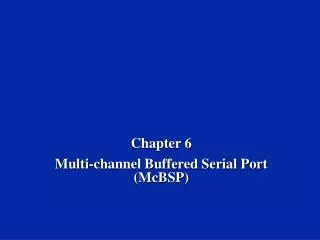
THE 8085 INTERRUPTS 15 • The 8085 has 5 interrupt inputs. • The INTR input. • The INTR input is the only non-vectored interrupt. • INTR is maskable using the EI/DI instruction pair. • RST 5.5, RST 6.5, RST 7.5 are all automatically vectored. • RST 5.5, RST 6.5, and RST 7.5 are all maskable. • TRAP is the only non-maskable interrupt in the 8085 • TRAP is also automatically vectored
8085 INTERRUPTS TRAP RST7.5 RST6.5 RST 5.5 INTR INTA 8085 17
INTERRUPT VECTORS AND THE VECTOR TABLE 18 • An interrupt vector is a pointer to where the ISR is stored in memory. • All interrupts (vectored or otherwise) are mapped onto a memory area called the Interrupt Vector Table (IVT). • The IVT is usually located in memory page 00 (0000H - 00FFH). • The purpose of the IVT is to hold the vectors that redirect the microprocessor to the right place when an interrupt arrives.
19 • Example: Let , a device interrupts the Microprocessor using the RST 7.5 interrupt line. • Because the RST 7.5 interrupt is vectored, Microprocessor knows , in which memory location it has to go using a call instruction to get the ISR address. RST7.5 is known as Call 003Ch to Microprocessor. Microprocessor goes to 003C location and will get a JMP instruction to the actual ISR address. The Microprocessor will then, jump to the ISR location
THE 8085 NON-VECTORED INTERRUPT PROCESS 20 • The interrupt process should be enabled using the EI instruction. • The 8085 checks for an interrupt during the execution of every instruction. • If INTR is high, MP completes current instruction, and sends INTA (Interrupt acknowledge) signal to the device that interrupted • INTA allows the I/O device to send a RST instruction through data bus. • Upon receiving the INTA signal, MP saves the memory location of the next instruction on the stack and the program is transferred to ‘call’ location (ISR Call) specified by the RST instruction
THE 8085 NON-VECTORED INTERRUPT PROCESS 21 • Microprocessor Performs the ISR. • ISR must include the ‘EI’ instruction to enable the further interrupt within the program. • RET instruction at the end of the ISR allows the MP to retrieve the return address from the stack and the program is transferred back to where the program was interrupted.
THE 8085 NON-VECTORED INTERRUPT PROCESS 22 • The 8085 recognizes 8 RESTART instructions: RST0 - RST7. • each of these would send the execution to a predetermined hard-wired memory location:
RESTART SEQUENCE 23 • The restart sequence is made up of three machine cycles • In the 1st machine cycle: • The microprocessor sends the INTA signal. • While INTA is active the microprocessor reads the data lines expecting to receive, from the interrupting device, the opcode for the specific RST instruction. • In the 2nd and 3rd machine cycles: • the 16-bit address of the next instruction is saved on the stack. • Then the microprocessor jumps to the address associated with the specified RST instruction.
ISSUES IN IMPLEMENTING INTR INTERRUPTS 24 • How long must INTR remain high? • The microprocessor checks the INTR line one clock cycle before the last T-state of each instruction. • The INTR must remain active long enough to allow for the longest instruction. • The longest instruction for the 8085 is the conditional CALL instruction which requires 18 T-states.
ISSUES IN IMPLEMENTING INTR INTERRUPTS 25 • How long can the INTR remain high? • The INTR line must be deactivated before the EI is executed. Otherwise, the microprocessor will be interrupted again. • Once the microprocessor starts to respond to an INTR interrupt, INTA becomes active (=0). Therefore,INTR should be turned off as soon as the INTA signal is received.
ISSUES IN IMPLEMENTING INTR INTERRUPTS 26 • Can the microprocessor be interrupted again before the completion of the ISR? • As soon as the 1st interrupt arrives, all maskable interrupts are disabled. • They will only be enabled after the execution of the EI instruction. Therefore, the answer is: “only if we allow it to”. If the EI instruction is placed early in the ISR, other interrupt may occur before the ISR is done.
MULTIPLE INTERRUPTS & PRIORITIES 27 • How do we allow multiple devices to interrupt using the INTR line? • The microprocessor can only respond to one signal on INTR at a time. • Therefore, we must allow the signal from only one of the devices to reach the microprocessor. • We must assign some priority to the different devices and allow their signals to reach the microprocessor according to the priority.
THE PRIORITY ENCODER 28 • The solution is to use a circuit called the priority encoder (74LS148). • This circuit has 8 inputs and 3 outputs. • The inputs are assigned increasing priorities according to the increasing index of the input. • Input 7 has highest priority and input 0 has the lowest. • The 3 outputs carry the index of the highest priority active input.
MULTIPLE INTERRUPTS & PRIORITIES 29 • Note that the opcodes for the different RST instructions follow a set pattern. • Bit D5, D4 and D3 of the opcodes change in a binary sequence from RST 7 down to RST 0. • The other bits are always 1. • This allows the code generated by the 74366 to be used directly to choose the appropriate RST instruction. • The one draw back to this scheme is that the only way to change the priority of the devices connected to the 74366 is to reconnect the hardware.
THE 8085 MASKABLE/VECTORED INTERRUPTS 30 • The 8085 has 4 Masked/Vectored interrupt inputs. • RST 5.5, RST 6.5, RST 7.5 • They are all maskable. • They are automatically vectored according to the following table: • The vectors for these interrupt fall in between the vectors for the RST instructions. That’s why they have names like RST 5.5 (RST 5 and a half).
MASKING RST 5.5, RST 6.5 AND RST 7.5 31 • These three interrupts are masked at two levels: • Through the Interrupt Enable flip flop and the EI/DI instructions. • The Interrupt Enable flip flop controls the whole maskable interrupt process. • Through individual mask flip flops that control the availability of the individual interrupts. • These flip flops control the interrupts individually.
THE 8085 MASKABLE/VECTORED INTERRUPT PROCESS 32 • The interrupt process should be enabled using the EI instruction. • The 8085 checks for an interrupt during the execution of every instruction. • If there is an interrupt, and if the interrupt is enabled using the interrupt mask, the microprocessor will complete the executing instruction, and reset the interrupt flip flop. • The microprocessor then executes a call instruction that sends the execution to the appropriate location in the interrupt vector table.
THE 8085 MASKABLE/VECTORED INTERRUPT PROCESS 33 • When the microprocessor executes the call instruction, it saves the address of the next instruction on the stack. • The microprocessor jumps to the specific service routine. • The service routine must include the instruction EI to re-enable the interrupt process. • At the end of the service routine, the RET instruction returns the execution to where the program was interrupted.
MANIPULATING THE MASKS 34 • The Interrupt Enable flip flop is manipulated using the EI/DI instructions. • The individual masks for RST 5.5, RST 6.5 and RST 7.5 are manipulated using the SIM instruction. • This instruction takes the bit pattern in the Accumulator and applies it to the interrupt mask enabling and disabling the specific interrupts.
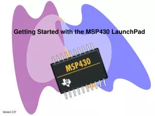
HOW SIM INTERPRETS THE ACCUMULATOR 7 6 5 4 3 2 1 0 M5.5 M7.5 M6.5 MSE SDO R7.5 SDE XXX } RST5.5 Mask 0 - Available 1 - Masked Serial Data Out RST6.5 Mask RST7.5 Mask Mask Set Enable 0 - Ignore bits 0-2 1 - Set the masks according to bits 0-2 Enable Serial Data 0 - Ignore bit 7 1 - Send bit 7 to SOD pin Force RST7.5 Flip Flop to reset Not Used 35
SIM AND THE INTERRUPT MASK 36 • Bit 0 is the mask for RST 5.5, bit 1 is the mask for RST 6.5 and bit 2 is the mask for RST 7.5. • If the mask bit is 0, the interrupt is available. • If the mask bit is 1, the interrupt is masked. • Bit 3 (Mask Set Enable - MSE) is an enable for setting the mask. • If it is set to 0 the mask is ignored and the old settings remain. • If it is set to 1, the new setting are applied. • The SIM instruction is used for multiple purposes and not only for setting interrupt masks. • It is also used to control functionality such as Serial Data Transmission. • Therefore, bit 3 is necessary to tell the microprocessor whether or not the interrupt masks should be modified
SIM AND THE INTERRUPT MASK 37 • The RST 7.5 interrupt is the only 8085 interrupt that has memory. • If a signal on RST7.5 arrives while it is masked, a flip flop will remember the signal. • When RST7.5 is unmasked, the microprocessor will be interrupted even if the device has removed the interrupt signal. • This flip flop will be automatically reset when the microprocessor responds to an RST 7.5 interrupt. • Bit 4 of the accumulator in the SIM instruction allows explicitlyresetting the RST 7.5 memory even if the microprocessor did not respond to it. • Bit 5 is not used by the SIM instruction
USING THE SIM INSTRUCTION TO MODIFY THE INTERRUPT MASKS - Enable 5.5 bit 0 = 0 - Disable 6.5 bit 1 = 1 - Enable 7.5 bit 2 = 0 - Allow setting the masks bit 3 = 1 - Don’t reset the flip flop bit 4 = 0 - Bit 5 is not used bit 5 = 0 - Don’t use serial data bit 6 = 0 - Serial data is ignored bit 7 = 0 M7.5 M6.5 M5.5 SDO MSE R7.5 SDE XXX 1 0 0 0 0 0 1 0 Contents of accumulator are: 0AH EI ; Enable interrupts including INTR MVI A, 0A ; Prepare the mask to enable RST 7.5, and 5.5, disable 6.5 SIM ; Apply the settings RST masks 38 • Example: Set the interrupt masks so that RST5.5 is enabled, RST6.5 is masked, and RST7.5 is enabled. • First, determine the contents of the accumulator
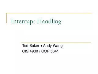
DETERMINING THE CURRENT MASK SETTINGS 7 6 5 4 3 2 1 0 SDI M5.5 M7.5 M6.5 IE P7.5 P6.5 P5.5 RST7.5 Memory RST 7.5 M 7.5 RST 6.5 M 6.5 RST 5.5 M 5.5 Interrupt Enable Flip Flop 39 • RIM instruction: Read Interrupt Mask • Load the accumulator with an 8-bit pattern showing the status of each interrupt pin and mask.
HOW RIM SETS THE ACCUMULATOR’S DIFFERENT BITS 7 6 5 4 3 2 1 0 M5.5 M7.5 M6.5 IE SDI P6.5 P7.5 P5.5 } RST5.5 Mask 0 - Available 1 - Masked Serial Data In RST6.5 Mask RST7.5 Mask RST5.5 Interrupt Pending RST6.5 Interrupt Pending Interrupt Enable Value of the Interrupt Enable Flip Flop RST7.5 Interrupt Pending 40
THE RIM INSTRUCTION AND THE MASKS 41 • Bits 0-2 show the current setting of the mask for each of RST 7.5, RST 6.5 and RST 5.5 • They return the contents of the three mask flip flops. • They can be used by a program to read the mask settings in order to modify only the right mask. • Bit 3 shows whether the maskable interrupt process is enabled or not. • It returns the contents of the Interrupt Enable Flip Flop. • It can be used by a program to determine whether or not interrupts are enabled.
THE RIM INSTRUCTION AND THE MASKS 42 • Bits 4-6 show whether or not there are pending interrupts on RST 7.5, RST 6.5, and RST 5.5 • Bits 4 and 5 return the current value of the RST5.5 and RST6.5 pins. • Bit 6 returns the current value of the RST7.5 memory flip flop. • Bit 7 is used for Serial Data Input. • The RIM instruction reads the value of the SID pin on the microprocessor and returns it in this bit.
PENDING INTERRUPTS 43 • Since the 8085 has five interrupt lines, interrupts may occur during an ISR and remain pending. • Using the RIM instruction, it is possible to read the status of the interrupt lines and find if there are any pending interrupts.
TRAP 44 • TRAP is the only non-maskable interrupt. • It does not need to be enabled because it cannot be disabled. • It has the highest priority amongst interrupts. • It needs to be high and stay high to be recognized. • Once it is recognized, it won’t be recognized again until it goes low, then high again. • TRAP is usually used for power failure and emergency shutoff.