Download
1 / 61
610 likes | 1k Views
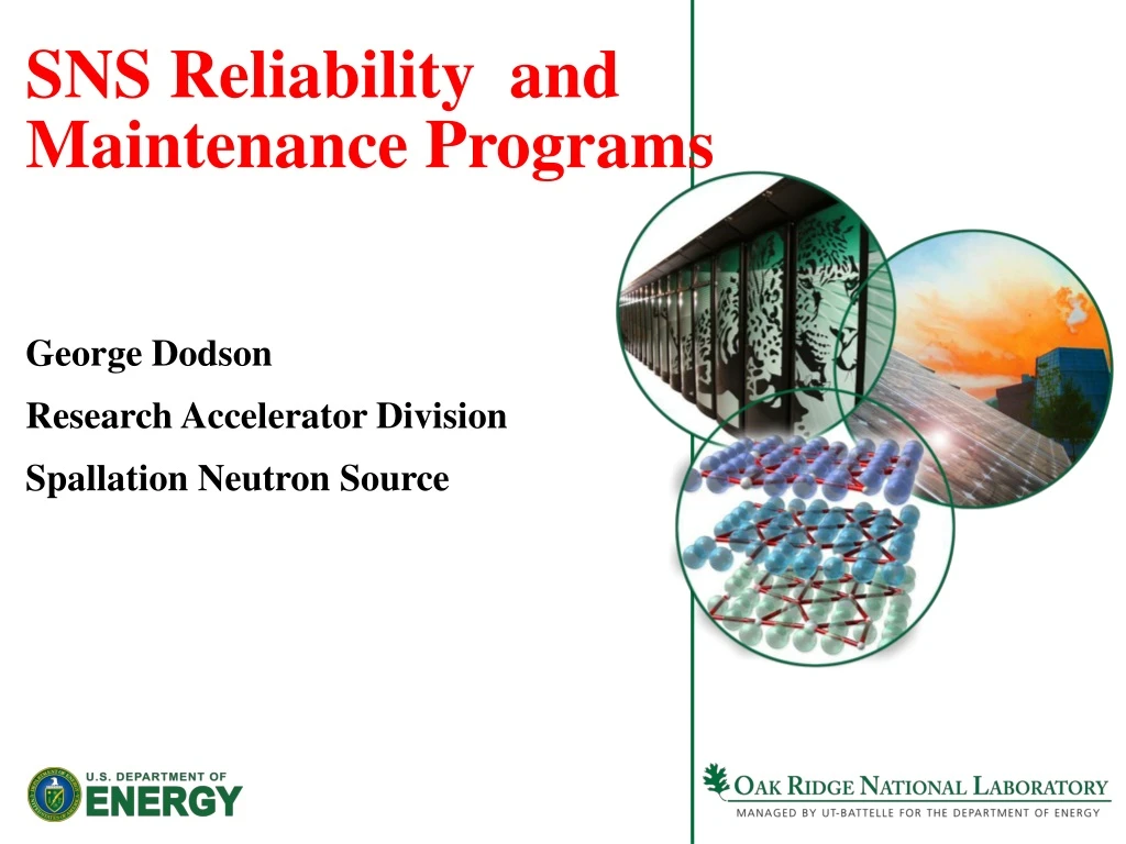
SNS Reliability and Maintenance Programs. George Dodson Research Accelerator Division Spallation Neutron Source. Topics. Vision and Goals Enablers Performance Metrics Management Information Systems Continuous Improvement RAMI Modeling Maintenance Management

E N D
SNS Reliability and Maintenance Programs George Dodson Research Accelerator Division Spallation Neutron Source
Topics • Vision and Goals • Enablers • Performance Metrics • Management Information Systems • Continuous Improvement • RAMI Modeling • Maintenance Management • Spares/Obsolescence/Vulnerability • Configuration Control
Vision The vision of the SNS Reliability and Maintenance Programs is an efficient, effective, reliable science facility throughout the lifetime of the SNS, currently expected to be ~40 years. Goals • The goals for Accelerator systems include: 4500 Hours of neutron production beam, at greater than 90% availability at or close to the nominal power delivery capacity of the SNS. • As the funding landscape shifts, achieving these goals will become more challenging. Increasingly greater demands are being placed on facility even as those staff are becoming leaner and in some cases less experienced due to retirements. As time passes, conditions change. Older equipment becomes obsolete and new equipment is added on a continuous basis. As a result, facilities are being operated and maintained under continually changing conditions. These changes will produce a new dynamic for our organization that adds to the facility maintenance challenges that we will face. • Our goals can be met in this challenging environment by developing best practices associated with an Integrated Maintenance Program structure and functionality. We must develop a maintenance processes that identifies causes of potential equipment failures, effectively monitors and assesses equipment condition, and proactively plans for equipment maintenance. This organization will more effectively utilize our staff by increasing their proficiency by applying standard processes, facilitating peer collaboration, completing databases to support condition-based maintenance, and documenting case histories.
Current 1ms SNS Accelerator Complex Front-End: Produce a 1-msec long, chopped, H- beam LINAC: Accelerates the beam to 1 GeV Accumulator Ring: Compress 1 msec long pulse to 700 nsec H- stripped to protons Deliver beam to Target 186 MeV 2.5 MeV 1000 MeV 87 MeV 387 MeV Ion Source CCL SRF, b=0.61 RFQ SRF, b=0.81 DTL Chopper system makes gaps 945 ns mini-pulse Current 1 ms macropulse Monthly Metrics for August, 2006
Enablers • The SNS Reliability and Maintenance Program is a facility-wide program for achieving the SNS primary beam delivery goals while maintaining and improving SNS Facilities in a cost-effective manner over the lifetime of the facility. The core of this program is a Reliability Centered Maintenance program. It is surrounded by a number of linked Management Information Systems (MIS), Other Systems and specific Policies and Procedures using applicable industrial standards. These systems include; • A Beam-time/Downtime Tracking System and Electronic Logbook • A Performance Metrics Reporting System • A Computerized Maintenance Management System (CMMS) • A Document Control System (DCS) linked to the CMMS • A Work Request/Planning/Scheduling System in or linked to the CMMS • A Reliability (RAMI) Modeling System • A Spares Plan linked to an Equipment Obsolescence Plan • A Vulnerability analysis of “single point” and/or “long time to recover” failures • A process for driving continued improvement in Equipment Design and Operation • A Configuration Control System to keep you from doing STUPID THINGS
Document Control Fault Reporting Major Components Goals Reactive Maintenance < 10% CMMS Performance Metrics Work Planning - Scheduling Preventative Maintenance 25-35% RAMI Model SNS Integrated Maintenance Program Reliability Centered Maintenance Predictive Maintenance 45-55% Spares Plan Configuration Control for Upgrades and New Equipment /Systems Equipment Obsolescence Plan Testing and Inspection FMEA Equipment Design Considerations Equipment Operations Considerations
Management Information Systems (Oracle) Acquire the Data • Beam Time Accounting • Operations Administration System (OAS) • Shift by Shift account of downtime • Electronic Logbook • Narrative account of shift activities including threaded discussion of breakdown and repair • CMMS – DataStream 7i (Infor) • Equipment Tracking • Asset Structure tables with parent-child relationships • “Cradle to Grave” tracking by position, location, asset • Asset status (Installed, In-Repair, Spare, Disposed Of) • Work Control • Use the same “Data Structures” for each: System, Sub-System, Sub-Sub-System , Sub-Sub-Sub-System, Asset, Position. Location • All 3 MIS Systems “Tied Together” through the Work Order Numbers
Operations Metrics Report forSeptember 23-29, 2013(Run FY13-2) Research Accelerator Division Spallation Neutron Source
Unscheduled downtime for the last week ≥ 0.2 hrs. Unscheduled downtime by number of occurrences >1 (beam and non-beam downtime combined)
RTBT_Diag:BCM25I:Power60Beam power on Target (60 sec. average) for the last week 1.41792 MW peak
Machine Issues: • Ion source • Arcing causing 13 MHz and Edmp power supply trips • RFQ • Chiller 2 PID tuning (0.5 C overshoot when RF is turned off and back on) • Cryopumpregen • Verify all warm linac arc detectors are working properly • No ion pump faults in DTL2 without RF • DTL3 winair arcs and vacuum burst in the tank • If venting is necessary during 2 week shutdown then replace DTL2 IP202 • CCL2 klystron window arcs (not sure there is enough time) • Arcs have returned after waveguide polishing • CCL2 modulator • Still tripping (last trip was 9/30 on DFDC B flux saturated fault) • DTL6 tank turbo pump is off
Operations Administration System (OAS) Shift Reports E-Log entries and OAS Downtime are reported. Work Orders are created in the CMMS and entered in the E-Log. Downtime linked to Work Order Number in the OAS is reported in the Metrics Analysis Identifies Problem Areas Performance Metrics Fault Reporting Electronic Logbook (E-Log) Weekly Metrics and Machine Health Report Operational and Design Considerations List of Machine “Issues” Failure precursors are identified by increased trip rates Downtime and Trip Rates are evaluated in the Weekly Machine Health Report, The trend from the past week, 2 weeks ago and 3 week ago.
Management Information Systems (Oracle) Acquire the Data • Beam Time Accounting • Operations Accounting System (OAS) • Shift by Shift account of downtime • Electronic Logbook • Narrative account of shift activities including threaded discussion of breakdown and repair • CMMS – DataStream 7i (Infor) • Equipment Tracking • Asset Structure tables with parent-child relationships • “Cradle to Grave” tracking by position, location, asset • Asset status (Installed, In-Repair, Spare, Disposed Of) • Work Control • Use the same “Data Structures” for each: System, Sub-System, Sub-Sub-System , Sub-Sub-Sub-System, Asset, Position. Location • All 3 MIS Systems “Tied Together” through the Work Order Numbers
What Equipment Must be Tracked? 1. Is the equipment safety-related? 2. Is the cost of the equipment $2500 or more? 3. Is the equipment categorized as a Quality Level 1 or Level 2 item (Safety Related) 4. Does the equipment require preventative/predictive maintenance? 5. Does the equipment require periodic calibration? 6. Does the equipment contain electrical components, which are categorized as “unlisted electrical equipment,” and require inspection and approval? • Manufacturer, Model, Version and Serial Number • When was it built • What did it arrive • When and where was it installed (position, location) • When it was maintained and who maintained it • When did it fail, what was the root cause, who repaired it • Where is it, where has it been and when (position and location)
Receiving Tracking ID Number (barcode #) Vendor Data (Traveler) EPICS Control System Vendor Documents Devices (Position /Location) MIS Database of Equipment and Spares (Assets) Test Data Installation Data Fault History Maintenance History Cradle-to Grave Equipment Tracking Data in the CMMS Data are in Document Control System by Tracking Number Example CCL_Vac:IP204
CMMS Inventory Control Cradle-to-Grave Asset History Cradle-to-Grave Equipment Tracking Equipment Status Position-Location History Spares and Parts Management Warranty Information Tracking Work Requests/Authorizations Work Prioritization and Scheduling Work Planning Automated Time-Based PMs Resource Allocation and Scheduling Inspections/Testing Based PMs Automated Meter-Based PMs Work Documentation Post Maintenance Testing Work Execution Equipment Swaps Equipment Repair Maintenance Costs Tracking Maintenance Hours Tracking
Data Management Analyze and Use the Data • Build a robust data system for tracking and trending, including MTTF, MTTR, Spares Inventory, Fault Tracking, etc. • Comparison of MTBF/MTTR data with the Reliability Model and industrial standards with an eye to the root cause of failures with higher than expected failure rates. • Go after the highest sources of downtime • Effectively utilize Control System Monitoring Data – filtering and pattern analysis to Detect the Onset of Pre-Failure Behavior so that you can replace the component in a Maintenance Period
Modeling:Predict the Performance Data • Modeling sets Your Expectations for Reliability/Availability for a given design: • Static Model • Markov Chain Model • R(t) is Constant • MTBF/MTTR inputs from Vendor Information and Industrial Standards • Monte Carlo Model (many commercial models available) • R(t) is an input function. You get to pick where you are on the function. • Use Actual Performance Data to Validate the Model
Front End Ion Source
Use the Model: • Model subsystems, systems, eventually the whole machine • Initially use vendor data and commercial standards for MTBF • Play “what if’s” with redundant systems (Hot Spares) • Be certain that what you are building meets the customer’s requirements • As equipment breaks you can immediately assess the impact of the measured lifetime on overall availability • Use Weibull distributions with guesses at failure onset, failure rate after onset, initial stock of spares and resupply rate to predict Mean Time to Out of Stock. • With actual performance data, carefully monitor transitions in performance data from Infant Mortality to Reliable Operation to the onset of Terminal Mortality to refine model parameters and your spares inventory
Maintenance Management • Predictive/Preventive maintenance schedules based on accepted practices for standard equipment and experience/MTTF data for specialized equipment • Manufacturer data is NOT always the best • EPRI Database • Proactive replacement of equipment showing pre-failure behavior • Effective use of scheduled and discretionary weekly maintenance opportunities • Avoid “run to failure” – “replace/repair when possible” • Spares inventory, not too big, not too small, just right! • Proactive replacement of equipment at a pre-determined % of measured lifetime – mature facilities with lots of data
Configuration Control One of the worst things that you can do at a mature, operating facility is allow changes to the design basis that, though the Law of Unintended Consequences, causes a failure that prevents the facility from operating. • Corollary – Smart People Sometimes Do Dumb Things.
Work Control • The SNS Work Control System is based around Safety then Complexity • Regardless of the work being performed, the basic approach is the same: • Define the Scope of Work • Analyze the Hazards • Develop and implement Hazard Controls • Perform the Work • Perform Post Work Testing • Provide feedback and continuous improvement • Work is requested, approved, planned, executed, completed and closed out using the CMMS.
Work Levels Class 1 Safety Systems (Personnel Safety)
Configuration Control Policy • Configuration management (CM) is defined as a process for establishing and maintaining consistency of a configuration item’s performance, functional and physical attributes, and its documented configuration with its requirements, design and operation information throughout its lifetime. • Configuration management control begins with baselining of requirements, the Design Criteria Document (DCD and Design Change Notification DCN) processes, and ends with decommissioning of equipment. • Responsibility for Configuration Control of Systems, Structures, Components andSoftware (SSCS)resides (at the SNS)with the System Engineer.
Configuration Control Objectives • To document and provide full evidence of an SSCS’s previous history (when available) and present configuration including the status of compliance of an item to its physical and functional requirements. • To ensure that staff who operate, use, repair or maintain an SSCS or who have the potential to affect its configuration use correct, accurate, and current documentation. • To ensure that new designs and changes to existing designs for systems, structures, components and software utilize best engineering practice, follow from an approved set of specifications, and are appropriately documented. • To ensure that the deployment of a new SSCS or a change to an existing SSCS is authorized. • To ensure that the impact on performance due to the deployment of a new SSCS or a change to an existing SSCS is fully understood, and that the risks associated with the deployment are considered. • SNS Procedures • OPM 9.A-1 SNS Configuration Management Policy • OPM 9.A-2 Design Development Policy • OPM 9.A-3 SNS System, Structure, Component or Software Change Procedure
Spares – Cold Spares Critical Equipment is equipment which is essential to the facility mission, which is traditionally defines as greater than the nominal beam delivery at greater than ~90% availability for some number of operating hours per year. Spares must be identified for critical equipment. Classes of Spares • A “true spare” consisting of a “like for like or equivalent” “on the shelf, tested and ready to go “, “plug compatible” replacement unit. • A “like for like or equivalent” that is installed in some other system that is not required for operation of the accelerator systems e.g. a Test Stand that must be removed from where it is being used so that it can be used as a replacement for the failed unit. • A system structure or component that must be modified to be used as a spare. • A system structure or component that must be purchased to be used as a spare. Only a level 1“true spare” will not contribute to down time. In all other classes, demounting, modification or procurement of the replacement will necessarily contribute to downtime. Class 4 is referred to as an “out of stock” condition The number of spares should be based on a calculation but should never be 1 ( or you are guaranteed to break it while installing it). SNS OPM 9B.-1 RAD Spares Management Policy (DRAFT)
Obsolescence • You probably don’t want to think about this now but the MTTO is on the order of 3 years for some classes of electronics. • With the manufacturing world changing rapidly, companies go out of business or are bought up and their product lines discontinued at an alarming rate. When they do your new replacements and product support may go to zero. • Obsolescence Definitions: • Supported: • Identical New Items/Repair/Parts are available from the OEM • Obsolescent: • New/Repair/Parts will no longer be supplied by the OEM after a given date. Sometimes you are even notified in advance! • Obsolete: • New Items/Repair/Parts are no longer available from the OEM • Obsolescence issues should be considered in the item life cycle to avoid risk. This means: • Assess the impact, cost and probability of obsolescence • Derive a Strategy • Reactive – do nothing until the need arises - Emulate/Partial Redesign/Replace • Proactive – Adopt a proactive strategy – Partial Redesign/Technology Transparency/Contract Support/Lifetime Buy • Periodically review and monitor the situation and act accordingly.
Types of Maintenance Reactive Maintenance Reactive maintenance is basically the “run it till it breaks” maintenance mode. No actions or efforts are taken to maintain the equipment as the designer originally intended to ensure design life is reached. • Advantages • Low initial cost. • Less staff. • Disadvantages • Increased unplanned downtime of equipment. • Increased labor cost due to overtime needed for call-in repairs • Possible secondary equipment or process damage from equipment failure. • Inefficient use of staff resources.
Preventive Maintenance Preventive maintenance can be defined as follows: Actions performed on a time- or machine-run-based schedule that detect, preclude, or mitigate degradation of a component or system with the aim of sustaining or extending its useful life through controlling degradation to an acceptable level. • Advantages • Cost effective in many capital-intensive processes. • Flexibility allows for the adjustment of maintenance periodicity. • Increased component life cycle. • Energy savings. • Reduced equipment or process failure. • Estimated 12% to 18% cost savings over reactive maintenance program. • Disadvantages • Catastrophic failures still likely to occur. • Labor intensive. • Includes performance of unneeded maintenance. • Potential for incidental damage to components in conducting unneeded maintenance.