Download
1 / 41
410 likes | 587 Views
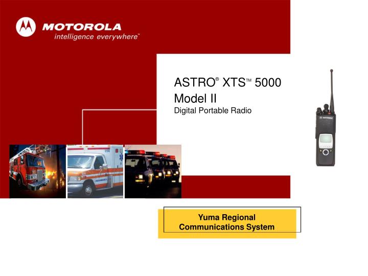
Cover. ASTRO ® XTS TM 5000 Model II Digital Portable Radio. Yuma Regional Communications System. Your Radio. 2-Position Concentric Switch Unprogrammed. 16-Position Select Knob. Power On/Off Volume Control. 10 : 46AM. YPD Patrol ChapmanR. Control Top. BATT. ZONE. PROG.

E N D
Cover ASTRO® XTSTM 5000 Model II Digital Portable Radio Yuma Regional Communications System
Your Radio 2-Position Concentric Switch Unprogrammed 16-Position Select Knob Power On/Off Volume Control 10 : 46AM YPD Patrol ChapmanR Control Top BATT ZONE PROG 3-Position Toggle Zone Select Top Button Emergency Side Buttons Top Side Button Cnv: Monitor Trk: Site Display Side Button 1 Volume Set Side Button 2 Cnv: TalkAround/Direct Trk: Keypad Lock Push-To-Talk (PTT) Button Menu Options Top Button Options Call Alert Page (Respond) Call Alert Page (Send – One-Touch) Call Alert Page (Send) Call Response Direct/TalkAround Display Light Dynamic Priority Emergency ID Number (View Your) Using Call Button ID Number (View Your) Using Page Button Monitor Nuisance Channel Delete Phone Call (Place – One-Touch) Phone Call (Place) Phone Call (Respond) Private Conversation Call (Place – One Touch) Private Conversation Call (Place) Private Conversation Call (Respond) Reprogram Request Scan On or Off Site Lock Site View/Search Status/Message Calls Talkgroup Calls Volume Set Tone
Status Symbols – 1 of 2 Signal Strength Direct/ TalkAround Monitor Scan Battery Status View Program Secure Call Receive Continued....
LED Status • RED • Solid • - PTT is pressed; radio is transmitting • Flashing • - Channel Busy • - Low Battery (lights while transmitting) • GREEN • Solid • - Self-test being performed • Flashing • - Incoming Private Call RED LED GREEN LED
Installation andRemoval Procedures Belt Clip Battery Antenna Public Safety Speaker Microphone Universal Connector RF Adapter
Antenna • To install the antenna: • Turn the radio off. • Screw the antenna (clockwise) into the antenna receptacle on top of the radio. • Tighten the antenna firmly with your fingers. • To remove the antenna: • Turn the radio off. • Unscrew the antenna (counter-clockwise) and remove it from the antenna receptacle on top of the radio.
Charging the Battery The battery must be charged before use. Memory effect is a phenomenon that causes a loss in battery capacity or voltage due to repetitive shallow discharging or long-term overcharging. This memory effect has been greatly reduced in your batteries through the use of new cell technology. It is still recommended, however, that you discharge your battery as much as possible before recharging it. Recharging after each shift is good standard practice. When charging a battery that is attached to your radio, turn the radio off to ensure a full charge. Battery procedures continued on next panel.
Battery • To install the battery: • Turn the radio off • Hold the radio with the back facing upward. • Align the three slots at the top of the battery with the three tabs on the back of the radio. • Push the battery down toward the radio until the battery clicks into place. • To remove the battery: • Turn the radio off. • Hold the radio with the back of the radio facing upward. • Push the battery release button on the bottom of the radio. • Lift the battery away from the radio and remove.
Universal Connector Cover • The universal connector cover protects the side • connector near the antenna. • To remove the cover: • Turn the radio off. • Carefully insert a flat-bladed screwdriver between the bottom of the cover and the connector. • Holding the top of the cover with your thumb, push the screwdriver gently downward and lever the cover away from the radio. • To install the cover: • Turn the radio off. • Insert the hooked end of the cover into the slot above the connector. • Rub the ball of your thumb from the top to the bottom of the cover, applying pressure towards the radio. This will flex the cover and snap it into place.
Belt Clip • To install the belt clip: • Remove the battery before installing or removing the belt clip. • Hold the battery with the back of the battery facing you. • Hold the belt clip with the top facing upward, and align the clip with the slots on the battery back. • Slide the belt clip downward into the slots until it clicks into place. • To remove the belt clip: • Pull away the metal tab at the top of the battery clip from the battery. • Slide the clip upward until it comes away from the radio. 1 2
RF Adapter (RFA) • To install the RF adapter (RFA): • Turn the radio off. • Remove the antenna. • With your hand above the RFA, hold the RFA in the upright position using your thumb and finger and position it on the radio antenna bushing. • Turn the RFA collar and housing (together) clockwise to engage the collar with the threads on the outside of the radio antenna bushing. Turn it until it has rotated between one and two full turns. Watch the position of the collar and connector target to count the number of turns. If it becomes difficult to turn, DO NOT FORCE IT. • While maintaining downward pressure on the properly oriented switch housing, place the custom wrench all the way onto the RFA collar’s wrench flats. The wrench will be captured by the collar and will be unable to slip upward or downward. Turn the wrench in increments until the RFA is tightened very securely to the antenna bushing (10-14 turns).
Public SafetySpeaker/Microphone Fix Note: When mic is installed, volume and channel buttons are disabled on the radio. Must be contralled on the mic. Note: Side buttons on mic are same as the side buttons on the radio Emergency Decrease Volume Increase Volume Volume Set Cnv: Direct Trk: Keypad Lock
Public SafetySpeaker/Microphone Installation(PSSM) – 1 of 3 • To install the PSSM: • Turn the radio off. • Follow the instructions for removing the universal connector cover. • Attach the accessory connector to the radio’s universal connector as follows: • a. Make sure the RF adapter has been installed in your radio before continuing with installation. • b. Looking at the antenna side of the radio, insert the bottom hooked end of the accessory connector into the slot below the universal connector. • c. While holding the accessory connector seated in the bottom slot, pivot the top of the accessory connector toward the radio until its RF interface connector aligns with the circular contact target on the RF adapter, then engage the accessory connector’s spring-loaded latch in the radio’s top slot. • Continued....
Public SafetySpeaker/Microphone Installation(PSSM) – 2 of 3 • Attach the correct (frequency-sensitive) antenna to the PSSM by screwing the antenna’s threaded end into the threaded antenna jack on top of the PSSM’s housing. • Rotate the antenna clockwise into the jack until it seats firmly. • The public safety speaker/microphone performs best • when it is operated with the antenna above the user’s • shoulder. • To transmit using the public safety speaker/microphone, • press the PSSM’s PTT and speak into the microphone’s • grille area. The red light-emitting diode (LED) on top of the • radio will light, indicating that the radio is in the transmit • mode. • If a more permanent attachment is desired after the • accessory connector is latched to the radio, secure the • latch to the connector housing using the screw supplied.
Public SafetySpeaker/Microphone Installation (PSSM) – 3 of 3 • To remove the PSSM: • Turn the radio off. • Rotate the antenna counter-clockwise to unscrew it from the jack. • Remove the accessory connector by pivoting the top of the accessory connector away from the radio until it disengages from the RF adapter. • Follow the instructions for attaching the universal connector cover.
Radio On/Off/Volume To turn the radio on: Turn the On/Off/Volume Control knob clockwise. If the power-up test is successful, you briefly see SELF TEST, then the home display. If enabled, a power-up tone is also heard. If the power-up test is unsuccessful, you see ERROR XX/YY. (XX/YY is an alphanumeric code.) . To turn the radio off: Turn the On/Off/Volume Control knob counter-clockwise until it clicks. On/Off/Volume Knob SELF TEST
Channel/Mode Select(16-Position Select Knob) Channel/Mode Name To select a channel/mode: Turn the Channel/Mode Select knob to select the desired channel/mode. The new name will appear on the display. If the channel/mode you selected is unprogrammed, repeat the above step. Channel/Mode Select Knob YPD PATROL BATT ZONE PROG
Zone Select(3-Position Toggle Switch) • To select a zone: • Toggle the Zone Select switch to select the desired zone. • If the zone you selected is unprogrammed, repeat the above step. Zone Name YPD PATROL BATT NOTE: This is a quick way to select the first three zones. Additional zones may be selected from the menu. ZONE PROG Zone Select Switch
Time-out Timer • The time-out timer turns off your radio’s transmitter. • The timer is set for 30 seconds at the factory, but it • can be programmed from 0 to 7.75 minutes (465 • seconds) by a qualified radio technician. • Hold down the PTT button longer than the programmed time. • You will hear a low-pitched warning tone, the • transmission will cut off, and the LED will go out until you • release the PTT. • Release the PTT button. • The LED will re-light and the timer will reset. • Press the PTT button to re-transmit. The time-out timer restarts. • The timer will restart and the LED lights red. LED Push-to-Talk (PTT)
Transmit and Receive • To transmit: • Select the desired zone/channel. • Listen for ongoing conversations; if the channel becomes clear, proceed with your call. • Press and hold the PTT button to transmit and wait for the “Talk Permit” tone. The LED will light red. When speaking, keep the microphone 1-2" from your mouth. • Note: If you do not hear a Talk Permit tone, your system • administrator has preprogrammed the tone to be off. • Release the PTT button to receive (listen). LED Push-to-Talk (PTT)
Emergency – SendEmergency Alarm(Top Button) • To initiate an emergency: • 1. Press the Emergency button. A tone sounds and the display • Alternates EMERGENCY with the current zone/channel, the LED lights red, and you hear a group of short, medium-pitched tones. • 2. Mic will be open for 10 seconds, announce your emergency. After 10 seconds press the PTT button to continue your emergency traffic. • 3. After completing the emergency call, press and hold the emergency button for one second. • The alternating EMERGENCY display disappears, and the radio returns to normal operation. • NOTE: Emergency call will revert to the emergency channel. Mic will be open for 10 seconds. • NOTE: You must shut off emergency before changing modes or you will continue sending alarms. EMERGENCY BATT ZONE PROG LED Emergency Button
Monitor (Conventional) (Top Side Button) • Your radio may be programmed to receive Private • Line(PL) calls. • To enable the monitor feature: • Select a conventional channel from the fleet map list provided by your system administrator. • Momentarily press the Monitor button to listen for activity. • The monitor/carrier squelch indicator ( )is displayed. • Press and hold the Monitor button (for a preset amount of time) to set continuous monitor operation. • Note: The duration of the button press has been • preprogrammed. Please see your System Administrator. • Press the Monitor button again, or the PTT button, to return to the original squelch setting. • Note: If you try to transmit on a receive-only channel, you • will hear an invalid tone until you release the PTT button. Monitor Button CONVENTIONAL Push-to-Talk (PTT) Push-to-Talk (PTT)
Site View/Search(Top Side Button) • You can view the number of the current site or force • your radio to change to a new one. • To view the current site: • Press the Site Search button. • The display momentarily shows the name of the current • site and its corresponding received signal strength • indicator (RSSI). • OR • If the radio is scanning for a new site, you momentarily see • SCANING SITE displayed. • To change the current site: • Press and hold down the Site Search button. • You momentarily see SCANING SITE displayed and hear • a tone. When the radio finds a site, it returns to the home • display. Site Search Button SITE 2 BATT ZONE PROG
Volume Set Tone(Side Button 1) • To adjust the volume: • Select the desired zone and channel. • Press and hold the Volume Set button to hear the volume set tone. • Adjust the Volume Control knob if necessary. • Release the Volume Set button. Volume Set Button On/Off/Volume Knob
Direct/TalkAround(Side Button 2) • Also known as “talk-around operation,” direct lets • you bypass the repeater and connect directly to • another radio. The transmit and receive frequencies • are the same. • To directly connect with another radio: • Select a conventional channel from the fleet map list provided by your system administrator. • Press the Direct button to enable this feature. • The direct symbol ( ) will be displayed. Make sure the • receiving unit has the same channel configuration • selected. You will not receive normal trunked, talkgroup • calls while in direct mode. • Press the Direct button again to disengage the feature and return to normal radio operation. • The direct symbol ( ) will no longer be displayed. Direct Button CONVENTIONAL BATT ZONE PROG
Keypad Lock (Side Button 2) • To lock or unlock the radio keypad: • Press the Keypad Lock button to lock or unlock the radio keypad. • Note: The keypad lock only locks the keypad, not any • other button or switch. Keypad Lock Button
Zone Select(Menu) • To select a zone: • Press the right side of the 4-way Navigation button • until ZONE appears on the display. • Press the button directly below ZONE. • The zone name flashes on the display. • Press the right side of the 4-way Navigation button to find the zone you want. • If the zone you selected is unprogrammed, repeat step 3. • Press the Home button to confirm the displayed zone and channel. • OR • Press the PTT button to transmit on the displayed zone/channel. Zone Name YPD PATROL BATT ZONE PROG Push-to-Talk (PTT)
Smart Battery(Menu) • This feature allows you to view the condition of your • Smart Battery. • To access information about your battery: • Press the right side of the 4-way Navigation button until BATT is displayed. • Press the button directly below BATT. • Battery data is displayed as follows: • CAPACITY indicates the current charge on the battery. • INIT indicates the date of the initial use of the battery. • EST CHGS indicates the estimated number of charges on • the battery. • Note: If a Smart Battery is not powering your radio, the • display will read SMART BATT DATA NOT AVAILABLE. YPD PATROL BATT ZONE PROG
Scan List Edit(Menu) – 1 of 3 • This feature lets you change scan list members and • priorities. • To edit the scan list: • Press button directly below PROG. • Press the button directly below SCAN • You see the first available item and the view/program ( ) • symbol flashing, indicating the programming mode. You • will also see SEL, DEL, and RCL displayed as possible • selections. • Continued.... YPD PATROL CALL PROG PHON
Scan List Edit(Menu) – 2 of 3 • Press the button directly below SEL or DEL or RCL. • SEL = add the currently displayed item to the scan list. • DEL = delete the currently displayed item from the scan list. • RCL = view the next available item. • Note: You cannot delete a priority member. • Continued.... YPD PATROL DEL SEL RCL
Scan List Edit(Menu) – 3 of 3 • Press the left or right side of the 4-way Navigation button to select more zones to be added or deleted. • OR • Use the 16-Position Select knob to select additional channels to be added or deleted. • Press the Home button to exit scan list programming and return to the home display. 16-Position Select Knob YPD PATROL
Nuisance Delete(NUIS Menu) • When the radio scans to a channel that you do not • wish to hear (nuisance channel), you can temporarily • delete the channel from the scan list. • To delete a nuisance channel: • Press the right side of the 4-way Navigation button until NUIS is displayed. • Press the button directly below NUIS to temporarily delete the displayed channel from the scan list while radio scans unwanted traffic. • If desired, re-enable the channel by exiting and re-entering scan. • Note: Nuisance delete cannot remove a priority channel • ( ) or the last channel in the list. YPD PATROL NUIS