Download
1 / 10
100 likes | 162 Views
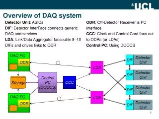
JParc-K DAQ System. Mircea Bogdan December 9-10, 2006. DAQ System - Block Diagram. Custom Boards: - ADC-125MHz, - FADC-500MHz, - Traffic Control, - System Trigger. CsI DAQ up to 2,816 Ch 14Bit/125 MHz : 11 Crates x 16 ADC Bds x16 Ch/Bd

E N D
JParc-K DAQ System Mircea Bogdan December 9-10, 2006
DAQ System - Block Diagram Custom Boards: - ADC-125MHz, - FADC-500MHz, - Traffic Control, - System Trigger. • CsI DAQ up to 2,816 Ch 14Bit/125 MHz : 11 Crates x 16 ADC Bds x16 Ch/Bd • Veto DAQ up to 512 Ch 14Bit/125 MHz : 2 Crates x 16 ADC Bds x16 Ch/Bd • BHPV DAQ up to 100 Ch 12Bit/500 MHz : 1- 4 Crates x 7 FADC Bds x4 Ch/Bd
DAQ System – Crate Block Diagram • Same Crate Configuration for all 3 DAQ Systems ; • All Crates: 6U VME 32/64 CBLT; • CsI and Veto DAQ – same boards, different firmware; • Beam Hole Phase Veto (BHPV) DAQ – different ADC Boards, different firmware.
12-Bit, 500MHz FADC Board – Block Diagram • Each FADC channel: one ATMEL - AT84AS001 chip: 12 bits/500MHz; • One STRATIX II FPGA can service up to 4 ADC channels : • After SERDES, data moved with 125MHz; • Trigger rate: 10kHz, 64 samples/trigger (128ns); • Input Pipeline: 25 -100us max depth (12,800 - 51,200 samples); • Two VME readout buffers - max 128 triggers each (10 ms); • Read Out Pulse in sync with VME, generate trigger time stamp; • FPGA device migration possible to increase/decrease max pipeline size;
14-Bit, 125MHz ADC Board – Block Diagram • Each ADC channel - one AD9445 chip: 14 bits/125MHz; • One STRATIX II FPGA can service 16 ADC channels: • Logic design and memory - similar to 500MHz FADC without SERDES; • Trigger rate: 10kHz, 32 samples/trigger (256ns); • Input Pipeline: 25 -100us max depth (3,200 – 12,800 samples); • Two VME readout buffers - max 128 triggers, (10 ms); • Read Out Pulse in sync with VME, generate trigger time stamp; • FPGA device migration possible to increase/decrease max pipeline size;
Readout Throughput 14Bit/125MHz ADC DAQ: 2,816 channels = 11 crates: • 16 ADC Boards/Crate x 16 ADC Channels/Board = 256 Channels/Crate. • 10 KHz trigger rate, 10% channel hit occupancy, 32 samples/trigger: • One channel: 10KHz x 10% x 2Bytes x 32samples = 64 KBPS; • 16-channel board: 1 MBPS/board • Crate with 16 boards: 16 MBPS - can be sustained via VME64 backplane; 12Bit/500MHz FADC DAQ: 25 -100 channels = 1-4 crates: • 6.25 FADC Boards/Crate x 4 ADC Channels/Board = 25 Channels/Crate. • 10 KHz trigger rate, 100% channel hit occupancy, 64 samples/trigger: • One channel: 10KHz x 12bits x 64samples = 0.96 MBPS; • 4-channel board: 3.84 MBPS/board; • Crate with 25 channels: 24 MBPS - can be sustained via VME64 backplane;
Preliminary FPGA Design Tests • High level of reuse between the two designs; many logic blocks are the same; • FPGA requirements: • About the same for: 4-ch,500MHz and 16-ch,125MHz boards; • May be larger on the 4-ch,500MHz board because of higher readout throughput per board; • Preliminary FPGA design tests on both boards with Altera EP2S60F1020C5 ($600): • 25us depth pipeline, two 32KBytes readout buffers (256Bits, 1024 words); • FPGA device migration possible on the same PCB: • With Altera EP2S90F1020C5 ($1,600): ~ 1.8 x memory; • With Altera EP2S130F1020C5 ($2,800):~ 2.7 x memory;
Board Manufacturing Cost Estimate • 176 pieces ADC-125 Board, 16-ch,125MHz, 6U VME, with EP2S60F1020C5($600): • $1,600(parts) + $300(pcb) + $500(assy) = $2,400/board = $150/channel; • 7-25 pieces ADC-500 Board, 4-ch,500MHz, 6U VME, with EP2S130F1020C5($2,800): • $3,800(parts) + $300(pcb) + $500(assy) = $4,600/board = $1,150/channel; • (with EP2S60F1020C5, the price drops to $2,400/board = $600/channel); • 14-17 pieces Crate Traffic Controller (CTC) Board: • $1,600(parts) + $300(pcb) + $500(assy) = $2,400/board; • 1-2 pieces System Trigger Module Board: • $4,000(parts) + $3,000(pcb) + $3,000(assy) = $10,000 for 2 boards; • 1 Piece 6U VME-VIPA Crate with Power Supplies and Crate CPU: • $12,500.
JParc-K DAQ System Cost Estimate(Full Cost: Engineering + Prototyping + Manufacturing) • CsI System with 3,000 channels, Crates, CPUs, ADC-125 boards: • Total cost: $860,000 i.e. $285/channel; • Veto DAQ with 512 channels, Crates, CPUs, ADC-125 boards: • Same ADC boards with different firmware; • Total cost: $115,000 i.e. $230/channel; • Beam Hole Phase Veto (BHPV) DAQ: • with 50 channels, Crates, CPUs, ADC-500 boards: • With EP2S60F1020C5: $230,000 i.e. $4,600/channel; • With EP2S130F1020C5: $260,000 i.e. $5,200/channel; • with 100 channels, Crates, CPUs, ADC-500 boards: • With EP2S60F1020C5: $290,000 i.e. $2,900/channel; • With EP2S130F1020C5: $360,000 i.e. $3,600/channel; • 15 pieces Crate Traffic Controller (CTC) Board: • Total Cost: $143,000; • 2-3 pieces System Trigger Module (STM) Board: • Total cost: $105,000; Total DAQ System Cost: ~ $1,500,000.
Design Examples 32 Ch, 18Bit/800kHz ADC Board 96 Ch, 1.2ns TDC Board Examples of DAQ Boards designed by UC Electronics Development Group 6 Ch, 8Bit/500MHz FADC Board