Download
1 / 48
610 likes | 1.15k Views
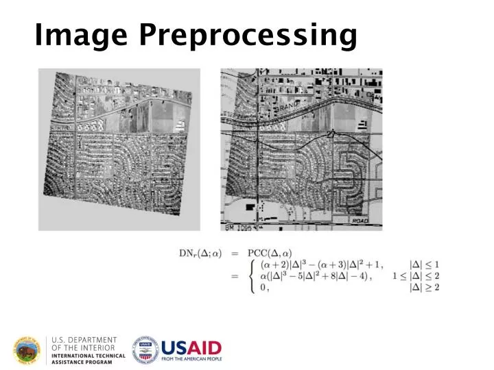
Image Preprocessing. Image Preprocessing. Learning Objectives. Be able to describe when and why image corrections are appropriate or necessary Give examples of some common approaches to image correction Understand the processing steps of Landsat data. Image Preprocessing.

E N D
Image Preprocessing Image Preprocessing
Learning Objectives Be able to describe when and why image corrections are appropriate or necessary Give examples of some common approaches to image correction Understand the processing steps of Landsat data
Image Preprocessing • Preprocessing is the removal of systematic noise from the data (Rees, 2001). It is the first step in the image processing chain and is usually necessary prior to image classification and analysis. GOAL : following image preprocessing, all images should appear as if they were acquired from the same sensor
Preprocessing Steps • Noise reduction/data loss correction • Atmospheric Correction • Radiometric Calibration • Geometric Correction
Preprocessing Steps • Noise reduction/data loss correction • Atmospheric Correction • Radiometric Calibration • Geometric Correction
Noise Reduction • Two types of noise: global and local • Global noise = random DN variation at every pixel - can be reduced using filters (moving windows) or Fourier transform • Local noise may include errors such as : • Missing scan lines • Image striping
Missing Scan Lines • Cause: Sensor timing failure • Solution: Interpolate to fill in the missing data. • Missing scan line pixel values are estimated using the values of the pixels in the lines above and below the missing line (based on the principle of spatial autocorrelation)
Striping • Caused by an imbalance in detector gains and offsets • Solution: re-calibrate sensors (adjust pixel DNs from each detector to yield the same mean and standard deviation over the entire image)
Preprocessing Steps • Noise reduction/data loss correction • Atmospheric Correction • Radiometric Calibration • Geometric Correction
Atmospheric Correction • Reducing the effects of atmospheric conditions on the image values
The value recorded at a given pixel includes not only the reflected radiation from the surface, but the radiation scattered and emitted by the atmosphere as well (path radiance).
Atmospheric Correction • Landsat 8 Cirrus band • Used to identify cirrus clouds which may not be visible with the naked eye • May want to remove those areas when conducting analyses/research
Atmospheric Correction - tools Correction methods for reducing atmospheric effects • Tools for improving both local and global effects • May improve some areas but cause artifacts in others (overcorrect) • ERDAS and ENVI both have modules that are used for atmospheric effects
Atmospheric Correction • IMPORTANT : Some atmospheric effects can not be fixed! • Dense clouds • Smoke • Heavy shadows • Best to exclude these areas from the analysis
Atmospheric Correction – Global Correction Techniques • Dark object subtraction • Conversion to surface reflectance • Image Normalization
Dark Object Subtraction • Dark objects have little to no reflectance observed by the scanner, so the DN values represent path radiance or the influence of atmospheric effects. By subtracting the value of the DN in each band, you remove that artifact. Dark object
Conversion to Surface Reflectance • Requires knowledge of aerosol conditions at the time of the image acquisition • Use of radiative transfer models based on optical depths of ozone and particulates in the atmosphere • Not usually possible for historical analyses
COST model by Chavez • Based only on image statistics – does not require field based data of aerosol conditions • Also utilizes dark object subtraction ERDAS Model available
Image to Image Normalization • Normalize one or more images to a ‘base’ image • Choose bright, mid and dark image targets that will be consistent in all images • Extract values and run linear regression • Use linear equation to adjust the values from the other, non-base images
Image Normalization Image 2 brightness value Image 1 brightness value
Comparison of sample 1986/2000 image bright target values BEFORE normalization Comparison of 1986 and 2000 bright target values AFTER normalization
Preprocessing Steps • Noise reduction/data loss correction • Atmospheric Correction • Radiometric Calibration • Geometric Correction
Radiometric Calibration • Reduce inconsistencies across detectors and reduce noise caused by sensor calibration, sun angle, and other conditions • Useful for comparing across sensors or comparisons across time
DN (raw value from the sensor) Calibrate based on gain and offset values At-sensor radiance Requires: Earth-sun distance Solar zenith angle Exoatmospheric irradiance TOA Reflectance Requires: Knowledge of aerosol properties Radiative transfer model Surface Reflectance
Conversion to Radiance Radiance = gain * DN + offset which is also expressed as: Radiance = ((LMAX-LMIN)/(QCALMAX-QCALMIN)) * (QCAL-QCALMIN) + LMIN QCAL = DN From Landsat metadata
Lmin and Lmax values used to convert to radiance. Can also use the gain and offset coefficients
Conversion to Radiance Gain and offset values from Landsat metadata file
Solar ExoatmosphericIrradiance Values Radiance to Reflectance Conversion
Solar Zenith Angle Radiance to Reflectance Conversion Zenith angle = 90.0 – sun elevation
Preprocessing Steps • Noise reduction/correcting for data loss • Atmospheric Correction • Radiometric Calibration • Geometric Correction
Geometric Correction • Georeferencing • Image registration • Rectification/orthorectification
Georeferencing The process of assigning map coordinates to image data. The image data are not altered (i.e. DNs do not change assuming NN resampling). From ArcGIS Resources online http://resources.arcgis.com/en/help/main/10.1/index.html#//009t000000mn000000
Image Registration The process of making one image conform geographically to another image. The process may or may not involve rectification. In most cases, some form of geometric transformation will be necessary. This involves ‘warping’ the image using mathematical models. From ArcGIS Resources online http://resources.arcgis.com/en/help/main/10.1/index.html#//009t000000mn000000
Polynomial Transformations 1st-order polynomial equations 2nd-order polynomial equations
Orthorectification "Orthorectification is the process of removing the effects of image perspective (tilt) and relief (terrain) for the purpose of creating a planimetrically correct image. The resulting orthorectified image has a constant scale wherein features are represented in their 'true' positions. This allows for the accurate direct measurement of distances, angles, and areas."
Once orthorectified, analyst can extract data from the image. Scale and distance are now true.
Once orthorectified, analyst can extract data from the image. Scale and distance are now true.
Steps for Orthorectification • 1. Use DEM to locate ground control points • 2. Compute mathematical equation (geometric transformation) • 3. Measure the accuracy of the transformation • 4. Create a new output image by applying the mathematical equation to the pixel data and resampling
Image Resampling 3 common options; Nearest neighbor Bilinear interpolation Cubic convolution Process of converting the original image grid to a new image, either by projecting to a new coordinate system or altering the pixel dimensions
Resampling Methods Nearest Neighbor The pixel value of the output pixel is assigned to the closest input pixel (pixel center, really)
Resampling Methods Bilinear Interpolation The pixel value of the output pixel is based on the weighted distance to the 4 pixel values nearest the input pixel
Resampling Methods Cubic Convolution The pixel value of the output pixel is based on the weighted distance to the 16 pixel values (in a 4X4 array) nearest the input pixel
Preprocessing Landsat data Landsat data are currently corrected by USGS/EROS to level 1T which includes the following: • Geometric correction with ground control points for accurate ground location • Radiometric correction for accurate measurements at the sensor and no data loss • may still want to convert to TOA reflectance for climate change studies