Download
1 / 5
50 likes | 59 Views
ESS Bunker A concept for a common beamline interface. ISIS Engineering Group, February 2015. For illustration purposes a conceptual CAD model of the VOR instrument is used. Beam port centreline alignment marks in addition to laser tracker network.

E N D
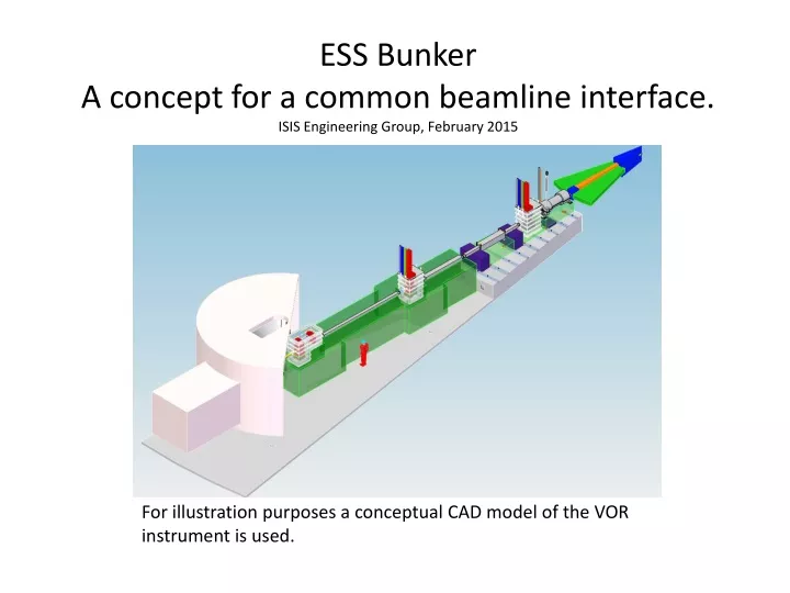
ESS Bunker A concept for a common beamline interface.ISIS Engineering Group, February 2015 For illustration purposes a conceptual CAD model of the VOR instrument is used.
Beam port centreline alignment marks in addition to laser tracker network Beam port height and centreline alignment marks Tapped holes or “T” slots to enable bolting down of components. ESS Bunker alignment concept. Levelled steel location rings protruding above concrete level and at 1m radial spacing containing dowel location pins in a radial pattern at 3° intervals. Lowered concrete levels to remove shine paths
How would this work? • Build leveled steel rings into the concrete base. • Fit all dowels as accurately as practical (±1mm). • Number, survey, and record all actual dowel locations. • Build beamline bases incorporating a dowel location hole and a location slot with location assisting chamfers (yellow). Ensure 3 feet to prevent rock (red)
How would this work? Continued… • Fit adjustable kinematic mounts (Cone, Vee, Flat) between beamline component and base. Adjustment to be on beamline component not base. • Fit laser tracker nests to top of beamline component such that it can be surveyed from above. • Offline set up 2 dummy dowel pins. Fit base and beamline component. Align onto beam centre relative to dowels and record tracker mount positions relative to beam center. Laser tracker nests Kinematic mounts Dowel location hole and slot
How would this work? Continued… • Install pre-surveyed bases and lower shielding components. • Locate beamline components onto pre-set kinematic mounts. • Confirm actual location & alignment using laser tracker from above. • To correct any alignment remove component and adjust offline using kinematic mount adjustment. • Re-install and confirm alignment with laser tracker. Shielding blocks coloured purple rest on the lowered concrete floor sections to remove radial neutron shine under the base shielding blocks David Turner 06/02/2015