Download
1 / 32
320 likes | 521 Views
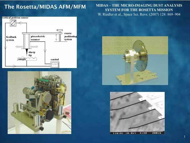
MIDAS – THE MICRO-IMAGING DUST ANALYSIS SYSTEM FOR THE ROSETTA MISSION W. Riedler et al., Space Sci. Revs. (2007) 128: 869–904. The Rosetta/MIDAS AFM/MFM. Characteristics of MIDAS AFM/MFM. 64 targets with resin surfaces 16 cantilevers/tips (4 magnetic), 1.6 mm apart

E N D
MIDAS – THE MICRO-IMAGING DUST ANALYSIS SYSTEM FOR THE ROSETTA MISSION W. Riedler et al., Space Sci. Revs. (2007) 128: 869–904 The Rosetta/MIDAS AFM/MFM
Characteristics of MIDAS AFM/MFM 64 targets with resin surfaces 16 cantilevers/tips (4 magnetic), 1.6 mm apart 100µ x 100µ x 7µ range Mechanical coarse approach Piezoelectric scanner Piezoresistive feedback Piezoelectric oscillators (dynamic mode)
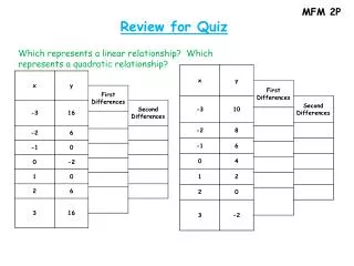
Ingesting the image files: Matlab Raw (left) and derivative (middle) plots of Image #3 using custom Matlab program. 3-D model (right) was plotted withhImageJ, an open-source, free utility. Matlab was used to convert the file to a PNG Empirically, data in file is little endian, organized in rows, starting at the top left. This needs to be documented.
Plotting in ImageJ Here, data is plotted as 3-D model with ImageJ, an open-source, free utility. Matlab was used to convert the file to a PNG, however.
SPIP Datafile format was chosen for compatibility with SPIP, an AFM community standard. Here, the provided file was directly imported into SPIP and rendered in 3D.
Images 1 and 2 in 3D (SPIP) These were heavily bowed, but correctible with SPIP After leveling, z-range was ~40 nm
NASAView (by Steele) #1 #2 #3
M. Hecht Review comments
Document: Coordinate System Fig. 3 This is a very helpful document, needing only a few improvements: The term “row” is used a numberof times, but is not defined Figure 3 (if I understand it) is so badly out of scale as to be deceptive. I suggest that instead of showing a full disk with oversized facets, simply show a small segment of arc with a realistic radius of curvature. There are still TBDs and TBCs in the definition of the AFM Reference frame It is stated that the reference position of the encoder corresponds to the center position of facet #1. Is this a good choice given that the reference position corresponds to the origin of the scan (e.g. a scan taken at the reference is in the upper right quadrant)?
Document: User Manual Very useful, though not always well tied to the dataset formats. Repeatedly refers to “silicon” damping material, where silicone is clearly intended
Document: ICD (General comments) • Scans are grouped into “observations.” The total information set for a given scan is thus contained in a set of files with: A prefix (HK_, IMG_, etc.); an observation designator (reflecting start and stop times); a scan number; and a suffix (reflecting extra information such as Channel ID). The most important are the IMG file, the HK files, and their corresponding label files. While this is implied in ICD Section 3.1.5 (File Naming Conventions), it should be clarified specifically at the start of the document.. • There is a general lack of narrative information. Much of the essential information is contained in PDS OBJECT descriptions, which are often generic, such as “Textual description of the event.” In that example, it would be useful to know what type of events might be captured in these records. • The filename contains a “sequence number,” and there are otherwise identical filenames with successive sequence numbers. Apparently a single “observation” can contain multiple successive scans. This needs documentation. • The authors seem to assume that users will use the IDL software alone. This software appears to collate and link the disparate information that makes up the context of the scan. It is strongly recommended that the documentation be adequate for users of other software to reconstruct the same information. • The use of the term “target” to refer to the substrate or coupon being imaged is ubiquitous. Unfortunately, it is also used to refer to the astronomical object under study (in TARGET.CAT, for example). It may be desirable to resolve this conflict.
ICD Section 2.4 (Overview of Data Products) Single Point Approach Data seems to describe a line scan rather than an approach. I can see how it might be applied to an approach, but this should be made explicit. Image Scan Data description is inadequate, considering that this is the primary data product. For one thing, there is no discussion of scan algorithms. Like a typewriter, an AFM scan must return to the start of every line (though some scan in a serpentine fashion). Typically data is collected during the return scan and interleaved “forward” and “backwards” images are acquired. If not, it is useful to indicate whether the data in the IMG file represents forward or backward. Also, as a result of the scan pattern and the possible need to stabilize the mechanism before beginning a new scan, either “scan speed” does not represent the actual time between data points, or else the product of scan speed and number of points does not equal the scan duration. This also should be documented. Target Utilization History Data: It is stated that each target is subdivided into 16 addressable segments, but doesn’t indicate the geometry of this subdivision (a figure would be helpful). Software (2.4.6) describes archiving of IDL-based routines in the PDS, which seems contrary to my understanding of PDS policy, as least how it was implemented for the Phoenix mission (with respect to Matlab-based routines). It was explained at the time that there is no guarantee that these routines will continue to operate as the closed-source environment evolves
ICD Section 3.2.4 (Other Applicable Standards) Oddly, this is where the description of the IMG format is found. It should be placed in a more appropriate Section. The IMG format includes several optional header items, among them “current,” which defines the tunneling current – a parameter inapplicable to an AFM. Extraneous parameters such as this should be removed from the description if they are not part of the MIDAS dataset, or at least prefaced by an indication that they are part of the SPIP standard but not used here.
ICD Section 3.4.2.2 (Calibration Directory) Here, description and offsets are listed but there is not description of the governing equation, hence the sign of the offset is unclear. It can be inferred that “value = data*calibration factor + offset,” but this should be explicit. Within the “description” column are (presumably) parenthetical ranges, but this is not indicated in the column header. Many calibration values don’t indicate data type (real, integer, etc.) or number of bits. This is presumably in the corresponding detailed descriptions, but a prose description would be appropriate as well since the data word type does not necessarily reflect the content (e.g. a 16-bit unsigned value may only have 12 bits of useful information).
IMG files (1 of 3) • The format has been chosen to conform to the proprietary SPIP data analysis program popular in the scanned probe community. However, the file description in the ICD is inadequate for users to develop their own code to read it. I was able to do so, somewhat by trial and error, determining the following: • Keywords are in the format “name=value,” one per line, with a space preceding and following the “=,”and with the value followed immediately by a <CR/LF> • The keyword list is padded to 2048 by a single string of zeros (not spaces). • The data is written in little endian format (indicated by the “intelmode=1” parameter), in 16-bit integers. The integers seem to be unsigned, as suggested by the LBL file SAMPLE_TYPE keyword value, “LSB_UNSIGNED_INTEGER.” • The data seems to be written in rows, with the first value representing the upper left of the image.
IMG files (2 of 3) • There should be a common section of the ICD with a complete description of the IMG file, rather than require the user to assembly the information from various sections. Some of the relevant information is only found in the User Manual (Section 3.1.9.2), such as these bullets: • Each value is stored in one word (16 bit). • All data acquired during one scan constitute a data set, i.e., a data set may contain up to 8 individual images. • The minimum size of an image is 32x32 pixels, filling 1024 words which corresponds to one image data packet. • The maximum size of an image is 512x512 pixels, filling 262144 words which corresponds to 256 image data packets. • The above might suggest that a single .IMG file may contain multiple channels. However, ICD Section 4.1.2 (Data Product Preparation) indicates that the IMG file has “one file per image and image data type.”
IMG files (3 of 3) I couldn’t find anything about completion status (it wouldn’t be unusual for a scan to be interrupted by, e.g., thermal drift taking the surface out of the narrow range of the z-piezo). DATA-QUALITY_ID and DATA_QUALITY_DESC in the IMG LBL file (ICD Section 4.2.3) seem to distinguish only “good” and “bad” data. I couldn’t find Channel Number (or the equivalent 2-letter code) or sequence number in either the LBL file or the IMG file header (unless it’s under MIDAS_SCAN_DATA_TYPE), only in the filename. It would be useful to have as a keyword, since filenames can be (and often are) changed by users.
HK and HK2 files A dictionary describing HK items in detail would be very helpful. These items are critical for interpreting the images, and in the present documentation there are only a few words associated with the DESCRIPTION keyword in the LBL file . It would be useful to have specific information (or a pointer to another file) indicating operation of other spacecraft systems that might be sources of microvibrations, as described in Section 3.1.5 of the User Guide.
Other files The sample Target History tables (TGH_) only include scanning events. Particle accumulation time would also be useful. It may be intended to include such information, but that underscores a general problem of the documentation. Since there is no narrative description of the various field in the tables, the reader can’t discern what types of information might be included.
Extra material Volume contents
ReadMe [TOP-LEVEL-DIRECTORY] | |-- AAREADME.TXT The text version of the AAREADME file. |-- VOLDESC.CAT Description of the contents of this volume. | |--[CALIB] Directory containing PDS calibration objects. | | | |-- CALINFO.TXT Description of files in the CALIB directory. | |-- MIDCALIB.LBL PDS label describing the MIDAS calibration table. | +-- MIDCALIB.TAB Standard MIDAS calibration table in PDS ASCII format. | |--[CATALOG] Directory containing PDS catalog objects. | | | |-- CATINFO.TXT Description of files in the CATALOG directory. | |-- DATASET.CAT Description of the MIDAS data set. | |-- INST.CAT Description of the MIDAS instrument. | |-- INSTHOST.CAT Description of the ROSETTA spacecraft. | |-- MISSION.CAT Description of the ROSETTA mission. | |-- PERSON.CAT Description of personnel who created this volume. | |-- REF.CAT List of publications mentioned in catalog files. | |-- SOFTWARE.CAT Description of S/W to read the data set. | +-- TARGET.CAT Description of the ROSETTA mission targets. |
ReadMe | |--[ROI] Directory containing MIDAS feature vector data. | | | | | |----- *.LBL Detached label files describing the data. | | +----- *.TAB MIDAS feature vector data files in binary format. | | | |--[SPA] Directory containing MIDAS DAQ approach data. | | | | | |----- *.LBL Detached label files describing the data. | | +----- *.TAB MIDAS DAQ approach data files in binary format. | | | |--[SPS] Directory containing MIDAS DAQ sampling data. | | | | | |----- *.LBL Detached label files describing the data. | | +----- *.TAB MIDAS DAQ sampling data files in binary format. | | | |-- CAH*.TAB MIDAS cantilever history files in ASCII format. | |-- TGH*.TAB MIDAS target history files in ASCII format. | +-- *.LBL Detached label files describing the data. | [|--[DATA] Directory containing the MIDAS data files. | | | |--[EVN] Directory containing MIDAS event data. | | | | | |----- *.LBL Detached label files describing the data. | | +----- *.TAB MIDAS event data files in ASCII format. | | | |--[FSC] Directory containing MIDAS frequency scan data. | | | | | |----- *.LBL Detached label files describing the data. | | +----- *.TAB MIDAS frequency scan data files in binary format. | | | |--[HK1] Directory containing MIDAS standard HK data. | | | | | |----- *.LBL Detached label files describing the data. | | +----- *.TAB MIDAS standard HK data files in binary format. | | | |--[HK2] Directory containing MIDAS extended HK data. | | | | | |----- *.LBL Detached label files describing the data. | | +----- *.TAB MIDAS extended HK data files in binary format. | | | |--[IMG] Directory containing MIDAS image data. | | | | | |----- *.LBL Detached label files describing the data. | | +----- *.BCR MIDAS image data files in STM-BCR format. | | | |--[LIN] Directory containing MIDAS line scan data. | | | | | |----- *.LBL Detached label files describing the data. | | +----- *.TAB MIDAS line scan data files in binary format.
ReadMe |--[DOCUMENT] Directory containing volume related documents. | | | |-- DOCINFO.TXT Description of files in the DOCUMENT directory. | |-- MID_*.LBL PDS labels for documents. | |-- MID_EICD.TXT MIDAS to PSA interface document in ASCII format. | |-- MID_EICD.PDF MIDAS to PSA interface document in PDF format. | |-- MID_EICD_*.PNG MIDAS to PSA I/F document images in PDS format. | |-- MID_SSRV.TXT MIDAS instrument paper in ASCII format. | |-- MID_SSRV.PDF MIDAS instrument paper in Adobe PDF format. | |-- MID_SSRV_*.PNG MIDAS instrument paper images in PNG format. | |-- MID_USER.TXT MIDAS user manual in ASCII format. | |-- MID_USER.PDF MIDAS user manual in Adobe PDF format. | |-- MID_USER_*.PNG MIDAS user manual images in PNG format. | |-- MIDAS_SW.LBL PDS labels describing MIDAS S/W source modules. | |-- *.PRO MIDAS archiving S/W source modules (IDL). | +-- Others Other documents (TBW). | +--[INDEX] Directory containing index files. | |-- INDXINFO.TXT Description of files in the INDEX directory. |-- INDEX.TAB Index table of MIDAS data in this data set. +-- INDEX.LBL PDS label for INDEX.TAB file. Contact Information =================== Lead Scientist : Klaus Torkar Austrian Academy of Sciences/Space Research Institute
Extra material AFM on Phoenix Lander
The Microscopy, Electrochemistry, and Conductivity Analyzer (MECA) Originally the Mars Environmental Compatibility Assessment for the 2001 Mars Surveyor Lander MECA enclosure Sampling chute Optical Microscope OM LEDs AFM SWTS 12 cm
Sampling chute with Sample Wheel sticking out Optical Microscope (OM) Part of Flight Sample Wheel showing different substrates and Safety Notch AFM sensor head and chip
Phoenix/MECA calibration scan, Sol 99-100 (new tip) 100-2 99-2 Small particle
Extra material Magnetic force microscopy
From The Potential of Magnetic Force Microscopy for in-situ Investigation of NanophaseIron in Lunar Dust, D. Kohl, G. Schittera, U. Staufer 2012 (submitted) Magnetic Force Microscopy