Download
1 / 37
440 likes | 496 Views
A presentation on topic thermal imaging

E N D
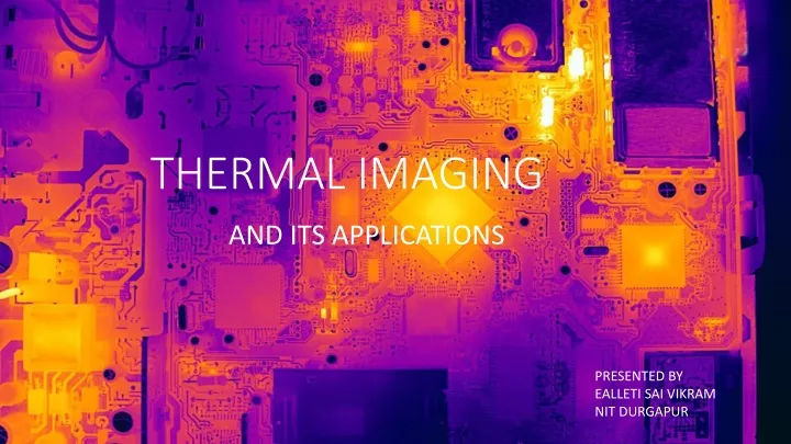
THERMAL IMAGING AND ITS APPLICATIONS PRESENTED BY EALLETI SAI VIKRAMNIT DURGAPUR
PRESENTATION AGENDA • Thermal Imaging • Infrared • Brief History Of IR • Infrared Detection • Bolometer • Infrared Camera Working • Impact of Emissivity on T.M • Spatial Resolution Definitions • Applications • Limitations
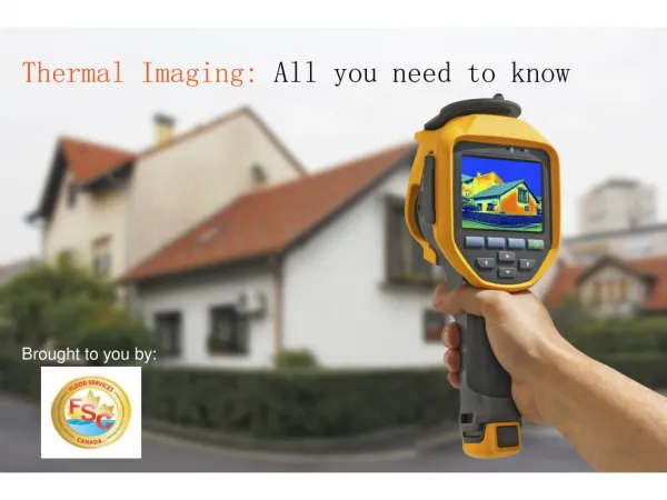
INFRARED OR THERMAL IMAGING • Thermal imaging is the technique of detecting infrared light (heat) given off by an object to produce a 2D image. It is an excellent example of visualization technique that can be used in many different fields of physics and science. • Requires absolutely no light. Totally unaffected by light sources.
INFRARED LIGHT • By understanding infrared, we can use thermal imaging devices to detect the heat signature of just about any object. • Nearly all matter emits at least a little bit of heat, even very cold objects like ice. That's because unless that object is at absolute zero , its atoms are still colliding around and generating heat. • This heat transfer occurs by release of photons and known as thermal radiation (EMR). • At low temperatures the objects do not glow but emit heat (i.e. mostly IR Radiation).
INFRARED DISCOVERY William Herschel
INFRARED DISCOVERY • In 1800, British astronomer named Sir William Herschel discovered infrared. • Throughout the1800’s, a series of intrepid thinkers experimented with materials that changed their conductivity when exposed to heat. This led to the development of extremely sensitive thermometers, called Bolometers. William Herschel
INFRARED DETECTION • The evolution of infrared cameras has diverged into two categories, calleddirect detection and thermal detection.
BOLOMETER A bolometer consists of an absorptive element made up of a thin metal layer. The absorptive element is connected to a thermal reservoir via a thermal link. When a radiation strikes the absorptive element, its temperatur`e is increased above the reservoir’s temperature due to the absorption of radiation by the absorptive element. Block diagram of Bolometer sensing setup ````
It is only the thermal isolation requirement (G) which sets micro bolometers apart from other temperature sensors which need to measure the surrounding temperature rather than incident radiation. Thermal isolation can be obtained by removing most of the underlying material as is done in bulk silicon micromachining (a sacrificial layer is removed in the last process step, thereby creating a suspended structure) .
INFRARED CAMERA WORKING • Camera sensor pixels are heated by incoming IR radiation. • Upon heating, pixel resistance varies. • The pixel resistance is measured and processing is done to calibrate temperature values. • Temperature value of each individual sensor is displayed in the form of IR map after post processing .
EMISSIVITY The emissivity of a given surface is the measure of its ability to emit radiation energy in comparison to a blackbody at the same temperature. It varies with material, roughness, wavelength, temperature, viewing angle.
SPATIAL RESOLUTION DEFINITIONS DSR – Distance to spot ratio FOV – What camera sees from a distance IFOV – Solid angle subtended by single pixel element ( units- mRad ) PIXEL PITCH – Size of the pixel element SPOT SIZE – What single pixel element sees at a given distance SPOT SIZE = (IFOV ) X (Distance of the target)
SPOT SIZE = (IFOV ) X (Distance of the target) SPOT SIZE IFOV Distance of the target
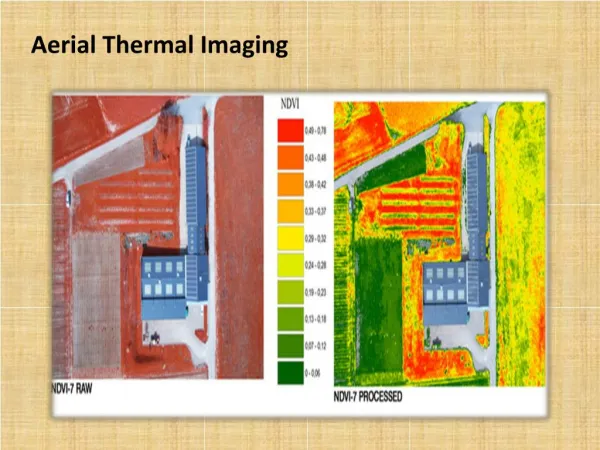
APPLICATIONS • Agriculture and Food processing industry • Condition monitoring • Fire fighting • Application in Building diagnostics (Construction) • Application in weather forecasting • Night vision • Energy management • Research • Volcanology • Electronic performance evaluation etc. • Defense Surveillance (UAV) • Search and Rescue operations • NDT • Medical • Surveillance (Crowded areas ) • Industry Process control • Level detection • Detect visually camouflaged target • Security and law enforcement • Wildlife management
WHAT ARE THE LIMITATIONS • Quality cameras are quite expensive. • Direct line of sight is needed for accurate result. • Wind can also affect the temperature rise. (> 5km/Hr) • It requires proficient skills to interpret the thermal • images obtained, especially the weather thermal images. • Accurate temperature measurements are hindered by • differing emissivities and reflections of other surfaces. Rs 42,000
All Optical Systems reach a limit in their ability to resolve very small objects efficiently • Can you read the smallest text above? • Would binoculars help? • All optical systems have limits in their ability • to detect ,recognize, and identify objects. • Infrared cameras are no different, except we • not only want to see small objects but we • also want to measure their temperature.
References Websites: https://www.flir.com https://electronics.howstuffworks.com https://en.wikipedia.org www.Irtraining.eu www.eevblog.com www.youtube.com https://www.sciencedirect.com/topics/physics-and-astronomy/bolometers Books: Gerald C. Holst - Common Sense Approach to Thermal Imaging -SPIE Publications (2000) Webinars: FLIR Emissivity Webinar – Instrumart FLIR IR Cameras and Microscopy Webinar –Instrumart The thermograms were obtained from a number of sources.