Download
1 / 1
10 likes | 133 Views
Exploration of GLSL Shaders David Cornette Computer Science Department Faculty Advisor: Dr. Bruce MacLeod. What is GLSL?

E N D
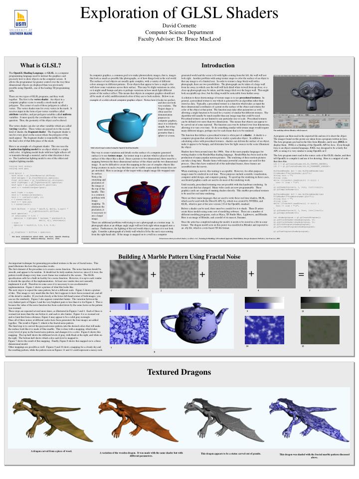
Exploration of GLSL ShadersDavid CornetteComputer Science DepartmentFaculty Advisor: Dr. Bruce MacLeod What is GLSL? The OpenGL Shading Language, or GLSL, is a computer programming language used to instruct the graphics card precisely how to draw objects on the computer screen. It allows the programmer far greater control over the way three dimensional objects are displayed than was previously possible using OpenGL, one of the leading 3D programming APIs. There are two types of GLSL programs, and they work together. The first is the vertex shader. An object in a computer graphics scene is usually a mesh made up of polygons. The corner of each of those polygons is called a vertex. The vertex shader runs for every vertex in the mesh. It receives input in the form of per-vertex variables called attribute variables, and per-polygon variables called uniform variables. It must specify the coordinates of the vertex in question. Thus, the geometry of the object can be altered. The vertex shader can also set other variables which are called varying variables. These values are passed on to the second kind of shader, the fragment shader. The fragment shader is run for every pixel on the screen where the polygons of the mesh appear. The fragment shader is responsible for setting the final color of that little piece of the mesh. Here is an example of a fragment shader. This one uses the Lambertian lighting model for an object which is a single solid color. A lighting model deals with how light reflects off or transmits through a material, and in what direction it does so. The Lambertian lighting model is one of the oldest and simplest lighting models. varying vec3 normal; varying vec4 pos; void main() { vec4 color = gl_FrontMaterial.diffuse; vec4 matspec = gl_FrontMaterial.specular; float shininess = gl_FrontMaterial.shininess; vec4 lightspec = gl_LightSource[0].specular; vec4 lpos = gl_LightSource[0].position; vec4 s = -normalize(pos-lpos); vec3 light = s.xyz; vec3 n = normalize(normal); vec3 r = -reflect(light, n); r = normalize(r); vec3 v = -pos.xyz; v = normalize(v); vec4 diffuse = color * max(0.0, dot(n, s.xyz)) * gl_LightSource[0].diffuse; vec4 specular; if (shininess != 0.0) { specular = lightspec * matspec * pow(max(0.0, dot(r, v)), shininess); } else { specular = vec4(0.0, 0.0, 0.0, 0.0); } gl_FragColor = diffuse + specular; } For more information about GLSL, see Rost, OpenGL Shading Language, Addison-Wesley, Boston, 2004. Introduction In computer graphics, a common goal is to make photorealistic images, that is, images that look as much as possible like photographs, or of how things look in the real world. The surfaces of real objects are usually quite complex, with a variety of different colors arranges in different patterns. Even objects that appear to have a single color will show some variations across their surface. This may be slight variations in color, or it might small bumps and pits or perhaps variations in how much light different points of the surface reflect. This means that objects in computer graphics should not all be made of solid, undifferentiated colors if they are to look realistic. Below is an example of a solid colored computer graphics object. Notice how it looks too perfect, generated world and the scene is lit with lights coming from the left, the wall will not look right. Another problem with using texture maps to color the surface of an object is that any image is of a limited size. In order to texture a large brick wall with a photograph, there are two possibilities. The photograph can be taken of a large wall from far away, in which case the wall will lack detail when viewed from up close, or a close-up photograph may be taken, and the image tiled over the larger wall. This might look acceptable up close, but the tiling would be noticeable from further away. A solution to these shortcomings of texture maps is to use procedural textures. In general, a procedural texture is one which is generated by an algorithm rather than stored as data. Typically, a procedural texture is a function which takes as input the three-dimensional coordinates of a point on the surface of the object and returns the color of the object at that point. The function may take other parameters as well, allowing a single function to be used for a variety of similar but different textures. The algorithm will usually be much smaller than any image map that could be used. Procedural textures are not limited to any particular size or scale. Procedural textures can be defined over more than two dimensions. This means that objects can appear to be carved out of some material. The function can even be defined over four dimensions, allowing it to vary over time. To do something similar with texture maps would require many different images, perhaps one for each frame that is to be rendered. The function that defines a procedural texture is often part of a shader. A shader is a computer program that calculates how to render a particular object. In addition to calculating colors with procedural textures, shaders can deform the surface of an object, make it appear to be bumpy, and determine how the light sources in the scene illuminate the object. Shaders have been around since the 1980s. One of the most popular languages for writing shaders is the RenderMan shading language. RenderMan has been used in the production of many popular motion pictures. The rendering of these motion pictures can take a long time. Render farms with many powerful computers are used for this process. Once they have rendered all of the individual frames, those frames are assembled into the movie. When rendering a movie, this waiting is acceptable. However, for other purposes images must be rendered in real time. These purposes include scientific visualization, computer aided design, and computer gaming. To speed up the rendering in these cases, accelerated graphics cards are used to do most of the rendering work. Until recently, procedural texturing was not possible with this hardware rendering. In recent years this has changed. Many video cards are now programmable. These graphics cards are capable of running shaders directly. This enables procedural textures to be used for real time rendering. There are three main languages that are used to write these real time shaders, HLSL, which can be used with the DirectX API; Cg, which was created by NVIDIA; and GLSL, which is part of the new version 2.0 of the OpenGL standard. Before a shader can be used, there must be a model for it to shade. Three D artists create these models using some sort of modeling software. There are a number of different modeling programs, such as Maya, 3D Studio Max, Lightwave, and Blender. Here is an image of Blender, and a model of its mascot, Suzanne. Once the artist has completed making the model, it needs to be stored in a file in some format. The dragon model seen on this poster was modeled in Blender and exported to an .obj file, which is a text-based 3D file format. and does not look very realistic. The Teapot shape is often used for demonstration purposes in computer graphics, since it is relatively simple, but it has more interesting geometry than a sphere or a torus. The modeling software Blender, with its mascot. A program can then read in the exported file and use it to draw the object. The images found on this poster are taken from a program written in Java. The Java program can load in the files from Blender, and it uses JOGL to display them. JOGL is a binding of the OpenGL API for Java. Even though Java is an object-oriented language, JOGL was designed to be a fairly flat API, so using it is very similar to using OpenGL in C. The Java program must read in the source code of the GLSL shader, and then tell OpenGL to compile it and use it for drawing. Here is a snippet of code that does this. int v = gl.glCreateShader(GL.GL_VERTEX_SHADER); int f = gl.glCreateShader(GL.GL_FRAGMENT_SHADER); BufferedReader brv = new BufferedReader(new FileReader("vertexshader.glsl")); String vsrc = ""; String line; while ((line=brv.readLine()) != null) { vsrc += line + "\n"; } gl.glShaderSource(v, 1, vsrc, (int[])null); gl.glCompileShader(v); BufferedReader brf = new BufferedReader(new FileReader("fragmentshader.glsl")); String fsrc = ""; String line; while ((line=brf.readLine()) != null) { fsrc += line + "\n"; } gl.glShaderSource(f, 1, fsrc, (int[])null); gl.glCompileShader(f); int shaderprogram = gl.glCreateProgram(); gl.glAttachShader(shaderprogram, v); gl.glAttachShader(shaderprogram, f); gl.glLinkProgram(shaderprogram); gl.glValidateProgram(shaderprogram); gl.glUseProgram(shaderprogram); Solid colored teapot rendered using the OpenGL fixed functionality. One way to create variations and details on the surface of a computer generated surface is to use texture maps. An texture map is a picture which is placed on the surface of the object like a decal. Since a picture is two dimensional, there must be a mapping between the three-dimensional surface of the object and the two dimensional image. It can be difficult to create this mapping in the case of complex objects like living creatures in such a way that there are no visible seams and the texture does not get stretched. Here is an image of the teapot with a simple image file wrapped onto its surface. Notice the stretching and pixelation of the image at the top of the handle. This is a common problem with image mapping. To eliminate the pixelation, it is necessary to use a larger image. There are additional problems with trying to use a photograph as a texture map. A photograph taken at an oblique angle angle will not look right when mapped onto a surface. Furthermore, the lighting of the real world object can cause it to not look right. Consider a photograph of a brick wall which is lit by the sun’s rays coming from the right hand side. If the image is mapped on to a wall in a computer To learn more about procedural shaders, see Ebert, et al., Texturing & Modeling: A Procedural Approach, Third Edition, Morgan Kaufmann Publishers, San Francisco, 2003. Building A Marble Pattern Using Fractal Noise An important technique for generating procedural textures is the use of fractal noise. This panel illustrates the how this procedure works. The first element of the procedure is to create a noise function. The noise function should be smooth, and appear to be random. It should not be truly random, however, since if it were, the pattern would change every time a new frame was rendered to the screen. The GLSL specification calls for a built-in facility for a noise function. However, it is up to each vendor to decide the specifics of the implementation. At least one vendor does not currently implement it at all. Therefore in some cases it is necessary to use an alternative implementation. Figure 1 shows a picture of what this looks like. The next step is to repeat the same pattern, but at a different scale. Figure 2 shows a picture of this. This image is very much like the first, but it appears to have been zoomed out, and all of the detail is smaller. If you look closely at the lower left-hand corner of both images, you can see the similarity. Figure 2 also appears somewhat fainter. The variation between the very darkest parts of Figure 2 and the very brightest parts is less than it is for Figure 1. This is because the value of the noise function has been scaled down by the same factor as the pattern was zoomed. These steps are repeated several more times, as illustrated in Figures 3 and 4. Each of these is zoomed out more than the one before it, and each is also fainter. Figure 4 is so zoomed out and so faint that from a distance, Figure 4 may appear to be a solid gray rectangle. Once all of these noises at different scales have been generated, the four images are added together. The result is Figure 5, which is the fractal noise pattern. The final step is to convert the grayscale noise pattern, into the desired colors that will make the surface look like it is made of blue marble. This is done with a mapping, which takes every level of gray in the fractal noise pattern, and changes it to a color. Figure 6 shows this mapping. The top half shows the different levels of gray, with black at the right, and white on the right. The bottom half shows which color each level is mapped to. Figure 7 shows the result of this mapping. Finally, Figure 8 shows this mapped on to a three dimensional model. Other mappings are possible as well. Figures 9 and 10 show a mapping for a cloudy sky and the resulting pattern, while the pattern seen in Figures 11 and 12 could represent a mossy rock. + + + = 1 2 3 4 5 6 9 11 10 12 7 8 Textured Dragons A dragon carved from a piece of wood. A variation of the wooden dragon. It was made with the same shader but with different parameters. This dragon appears to be a statue carved out of granite. This dragon was shaded with the fractal marble pattern discussed above.