Download
1 / 63
630 likes | 638 Views
Introduction to the SG-II. Installation and Service.

E N D
Introduction to the SG-II Installation and Service You can mouse click anywhere on a blank spot on a slide to move to the next slide, or use the Page Up / Page Down keys to move backward and forward. Clicking on underlined hyperlinkswill let you jump around. Click the Return button to get back. April 28, 2005
Contents Continue going through slides or select individual topics. It is recommended going through the complete presentation slide-by-slide the first time viewing. Introduction • Objective • Introduction • Precautions Features • SG-II features • PCI Interface • Beam Blank • X and Y Scan • External Scan Enable • RTEM/UMS-II Interface • Local Power • Microscope Beam Control • Signal Acquisition Boot Up • SG-II Driver Tests • Install Drivers • Installation and Setup • SG-II Installation • Imaging Installation Introduction • SG-2 Shell Introduction • SG-2 Panels • Microscope Signals • External Control • Video Blanking • Scan Settings • Analog Video • Input Collection Panel • Imaging Adjustments Procedure • Aspect Ratio Guide • Print Setup Parameters • SG-2 Shell Diagnostics • Diagnostics Introduction • About Shell • Required Test Equipment • Digital Video Loop Back • Analog Loop Back • Measure SG-II Voltages • Test Points, Jumpers, Pots, LEDs • Troubleshooting Voltage Measurements • Test Point Locations • SG-II LED Locations • External Connector • Check Device Manager • Check Event Viewer • Service Part Numbers • Part Numbers Return to Previous View This is useful if you hyperlink from one slide to another to see a particular feature. Note that it’s only good for one previous view, it doesn’t maintain a history.
Objective • This presentation introduces the Scan Generator board features and the procedures to be followed to install, service and troubleshoot potential problems. This presentation is developed for Service Engineers who will service and install Scan Generator boards. • More detailed information can be found in the Service and Installation and SG-2 Shell User’s Manuals. These manuals are included on this CD. This link will bring you back to Table of Contents Back to Contents
Introduction • The scan generator board is used to control the microscope scan functions as well as collect data related to imaging. The PCI Scan Generator, referred to as the SG-II, is the Imaging-only replacement for the EDI-II board. The SG-II eliminates the requirement of the Electron Microscope Interface Adapter (EMIA) to interface with microscopes. The SG-II replaces the EDI-II, using the same connections to the microscope. Some enhancements over the EDI-II include the following: • Motorized slide control • Video termination • Video coarse gain • Live spectrum mapping detector switching • Differential scan support • Output enable relays (EMIA elimination) • Built in analog and digital loop back • Built in power up tests • Generates all power from the PCI bus • The SG-II is not compatible with Windows NT, 98, or 95. There are no TTL inputs. Introduction continues
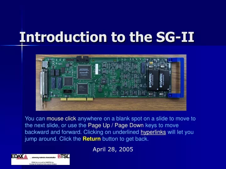
Introduction - SG-II Board Introduction continues
Introduction – Inside EDAM SG-II and DPP-II boards with cable for Live Mapping Introduction continues
Genesis Configurations • The SG-II board, fits into one of three basic Genesis series analyzers: • Genesis 2000 – EDAX boards are installed inside of the workstation • Genesis 4000 – EDAX boards are installed in a 4-slot expansion chassis with a host computer controller card, adheres to the micro ATX form factor and uses an industry standard ATX power supply with power factor correction. • Genesis 7000 – EDAX boards are installed in a 7-slot expansion chassis with a host computer controller card, adheres to the micro ATX form factor and uses an industry standard ATX power supply with power factor correction. Introduction continues
Edam Rear Panel SG-II board DB-37F (J2) + Mini 8F(J1) DPP-II FR board DB-9F + Mini 8F HV Bias board SHV BNC Connector Introduction continues
SG-II Configurations • SEM Only Configuration • In a Genesis SEM-Only configuration used only for beam control and video data, requires only an SG-II board installed along with interface cables. • EDS and SEM Configuration • When the Genesis system is to be configured for EDS and Scan Generator, a DPP board, SG-II and HV Bias board are used along with supporting cables. Back to Contents
Precautions ESD • ESD voltages as low as 60 volts can destroy state-of-the-art integrated circuits used on the SG-II. Always ground yourself to the equipment chassis before removing or replacing the boards. PCB repairs should always be preformed on a conductive surface with the repairman grounded, via a conductive strap with a built-in current limiting resistor, to this surface. OBSERVE ESD PRECAUTIONS, OTHERWISE DAMAGE WILL OCCUR!!! Hot-Swap • The SG-II is NOT hot swappable. The power to the system must be turned off before inserting or removing the boards or any of the interconnecting cables. If this precaution is not taken, components will be damaged nearest to the connecting pins. NEVER CONNECT/DISCONNECT CABLES FROM THE GENESIS SYSTEM WHILE POWER IS ON!!! Back to Contents
SG-II Features • The SG-II replaces the EDI-II, using the same DB37 connection to the microscope. Enhancements over the EDI-II include the following: • Motorized slide control • Video termination • Video coarse gain • Live spectrum mapping detector switching • Differential scan support • Output enable relays (EMIA elimination) • Built in analog and digital loop back • Built in power up tests • Generates all power from the PCI bus • The SG-II is not compatible with Windows NT, 98, or 95. Features continues
PCI Interface • The SG-II board communicates to the host computer using the PCI bus. It makes use of industry standard PCI Target devices along with some Non-Volatile RAM to store board specific PCI configuration data. All of the parameters for beam scanning, DAC values, time values, etc, are programmable by the host computer using the PCI interface. Back to Contents Features continues
Video Blank • This is an analog output signal to the microscope to prevent the beam from hitting the specimen. This output is programmable from +/- 15V and is driven off the board through a relay. The relay enable signal is controlled through the software. Additionally the output relay is capable of looping an external input back to the microscope. SG-II Control N.O. Beam Blank to Microscope N.C. SG-II board From microscope Back to Contents Features continues
External Scan Enable • This is an analog output signal to the microscope to put it in an external control mode. This output is programmable from +/-15 V and is driven off the board through a relay. The relay enable signal is controlled through the software. Additionally, the output relay is capable of looping an external input back out to the microscope. SG-II Control N.O. Ext Scan N.C. SG-II board From microscope Back to Contents Features continues
X and Y Scan • The X and Y Scan circuitry are identical circuits that control the scan voltages to the microscope. • The scan range is programmable from +/-15 Volts, 30 mA Max. • The scan can be configured for single-ended or differential drive. • There are on-board relays in the scan circuit to loop input scan signals back out to the microscope. Back to Contents Features continues
RTEM/UMS-II Interface • The SG-II board contains an on-board interface to drive the RTEM controller box by emulating the external button box or driving the UMS-II stepper motor. This provides a flexible slide interface to support the EBSD camera for the TSL applications. Back to Contents Features continues
Local Power • The SG-II board generates all of its required voltages from the PCI bus’s +5V power, VCC. The analog circuitry requires +/-5V and +/-15V which are generated from isolated DC/DC converters. The digital circuitry uses VCC as well as generating +3.3V and +1.8V. Back to Contents Features continues
Microscope Beam Control • The SG-II board contains the necessary circuitry to control two axes of the microscope beam. The scan circuit operates in several different modes and supports several different patterns. The beam control is split into two areas, the digital domain and the analog domain. Most of the functionality is accomplished in the digital domain, but the final analog voltages are manipulated in the analog domain to yield a large amount of control. Back to Contents Features continues
Signal Acquisition • While the SG-II is controlling the beam, the board is also capable of collecting data from different sources. There are bits in the control word of the SG-II board to select the active data sources. Some new features are listed here: Video Termination • The input video lines have an optional 75 ohm terminating resistor which is software selectable to improve the reflections on the video wires. Scan Loop Back • After the Video buffer is an analog switch to loop back the X and Y scan output to the Video 0 and Video 1 input respectively. This is provided for diagnostic purposes. Live Spectrum Mapping Mode • The SG-II supports Live Spectrum Mapping. The external EDS sub-system, DPP-II electronics, is treated as another video channel. Several channels can be connected. Back to Contents Features continues
Video Threshold Mode • The Video Threshold mode of Live Spectrum Mapping Mode operates the same as Live Spectrum Mapping, with one exception. After the Video has been completed, if the video level falls outside of some predetermined region, an Abort signal is sent to all of the EDS sub-systems for them to terminate their acquisitions immediately. Once that happens the SG-II resumes the scan as normal. Back to Contents Features continues
SG-II Driver Tests • The driver for the SG-II board, ep20000, contains several built-in low level tests to verify the operation of the SG-II board before any upper level operation may begin. If any of the built-in tests fail, a message is written to the Windows Event Viewer indicating the error with an accompanying code. • Use the My Computer icon on the desktop or the start menu to access the Windows Event viewer. Place the mouse over the My Computer icon, press the right mouse button and select the Manage option. The Computer management dialog box appears on the desktop. Driver Tests continues
Computer Management Computer Management Console Expand the Event Viewer entry under the system tools by clicking on the System entry under the System Tools. See next slide… Driver Tests continues
SG-II Event Viewer Event Viewer The SG-II driver will leave entries in the Event Viewer with a Source of ep20000. If an error has occurred at the driver level, the type in the Event Viewer will be Error. See next slide… Driver Tests continues
SG-II Event Errors SG-II Errors See next slide… Driver Tests continues
Event Log Error Details Event Log Error Details, Example Back to Contents Driver Tests continues
SG-II Installation • Observe ESD precautions when handling the board. • Do not install or connect any boards or cables with power ON. • Drivers for the SG-II are available in Genesis Version 4.51 or higher. • The SG-II is a full length PCI board that installs in a standard PCI bus. It draws power from the PCI bus. • Install the board in an available slot. It should be located near the DPP board if Live Spectral Mapping is to be used. • Do NOT connect the microscope interface cable yet! • After installation, the New Hardware Wizard should run after rebooting. If it does not, check the Device Manager, and EDAX Inc, for an instance of the SG-II. Run the driver install as follows: • Run Install.exe from c:\Edax32\Sys\Windows Driversor from the Windows Drivers folder on the Genesis CD (Version 4.51 or higher). Back to Contents SG-II Installation continues
Install Drivers Run Install • Run the driver installation by running Install.exefromc:\EDAX32\SYS\Windows Drivers or from the Windows Drivers folder on the Genesis CD. Back to Contents SG-II Installation continues
Check Device Manager This screen shows a SG-II board installed and recognized by Windows. Back to Contents Installation continues
Imaging Installation • The microscope interface is made via a cable to the SG-IIDB-37F J2external connector (Compatible with EDI-II). In most cases, this cable will connect directly to the microscope as the SG-II has output enable relays, video termination and differential scan support built in. • Set up the initial parameters BEFORE connecting the cable between the SG-II and the microscope. Back to Contents Installation continues
SG-2 Shell Introduction • To perform all of the adjustments needed for imaging, the SG-2 Shell program must be used. This is located in the C:\EDAX32\SG-2 directory. From the Windows Taskbar click on Start, Programs, EDAX Genesisandthen SG-2 Shell. When the application is loaded, the user will have to input the authorization password to use the software. • Only one instance of the SG-2 Shell may be run at a time. See the SG Shell User’s Manual for detailed use of the Shell. Back to Contents Installation continues
SG-2 Shell The figure here illustrates the SG-2 Shell’s main window. Back to Contents Installation continues
Panels for Imaging Setup • The SG-2 Shell contains an area on the right side of the window that has different panels for various operations depending on the mode selected. These panels are selected through either speed buttons or by the Panel menu options. • For the initial set up of the Shell, you select Panel from the menu bar, and set up the External Setup, Scan SetupandInput Setup panels with the values for the X and Y scans, External Enable, Video Blank, and Video Input Voltage levels, as documented in the Microscope Imaging Interface Addendum instructions for the specific microscope being interfaced to. Back to Contents Installation continues
Microscope Signals Reference This table shows the most common microscope signal adjustments. The actual voltage levels can be measured at the DB-37 J2connector on the board or at the X and Y Scan Test Points on the top edge of the board. Refer to the section on Microscope Interface in the Service Manual for a list of all microscope signals. Back to Contents Installation continues
External Control SG-2 Shell External Setup Panel This is selected by clicking on Panel on the menu bar, then External Setup. This allows the user to configure the voltage and output enable settings required to enable/disable external control on the microscope. The voltage range for external control is +/- 15 volts. The check box label “Ena” specifies the output enable setting. When checked, the external control line from the microscope is actively connected to the SG-II board. When unchecked, the signal line is disconnected from the SG-II board. Back to Contents Installation continues
Video Blanking • This allows the user to configure the voltage and output enable settings required to enable/disable video blanking to the microscope. The voltage range for video blanking is +/- 15 volts. The check box labeled “Ena” determines the output enable setting. When checked, the blanking line from the microscope is actively connected to the SG-II board. When unchecked the signal line is disconnected from the SG-II board. • These settings are made available from the External Setup panel. • This is selected by clicking on Panel on the menu bar, then External Setup. Back to Contents Installation continues
Scan Settings • The Scan Setup Panel allows the programming of the scan related parameters: Beam Park Mode, Line Sync, Drive Type, Gain, Offset, Retrace Delays, Inversion, Scan Strobe. • If any parameters are not specified by the Microscope Imaging Interface Addendum, leave the defaults to start. • The vertical scroll bar adjusts the parameter that is currently selected. The current parameter is indicated with the Green colored label. The current parameter is selected by clicking the mouse in the corresponding edit box. Back to Contents Installation continues
Analog Video • Each of the two analog video channels has a group of controls that determines that value obtained from the analog to digital conversion process. These parameters are coarse gain, gain, offset, signal polarity (invert), and 75 ohm termination (term). The vertical scroll bar adjusts the parameter that is currently selected. The current parameter is indicated with the Green colored label. The current parameter is selected by clicking the mouse in the corresponding edit box. • This panel is selected by clicking on Panel on the menu bar, then Input Setup. Back to Contents Installation continues
Input Collection Panel • In this panel, the mode, Matrix, Video, Number of Reads, Continuous collection and Inter-Pixel delay can be chosen and setup. • Some additional selections are for Analog and Digital Loop back for diagnostic testing purposes. • A new feature is the Live Map ADC Threshold. • This panel is selected by clicking on Panel on the menu bar, then Image Collection. Back to Contents Installation continues
Adjustments Procedure • For the initial set up of the Shell, select Panel from the menu bar, and set up the External Setup, Scan SetupandInput Setuppanels with the values for the X and Y scans, External Enable, Video Blank, and Video Input Voltage levels, as documented in the Microscope Imaging Interface Addendum instructions for the specific microscope being interfaced to. Set these parametersBEFOREconnecting the SG-II to the microscope! • Once the initial adjustments have been made in the SG-2 Shell, Power OFF the EDAM and connect the interface cablebetween the microscope and the SG-II board. Do not connect the cable with power ON the SG-II. Start the system back up to make further adjustments to match the microscope image with the image captured with the SG-II. • Setup the microscope with an image of a copper grid. Select a magnification that fills most of the image area with several grids. • If applicable for the microscope model, put the microscope in External Control mode, so the EDAX Scan Generator (SG-II) can control the scan. Installation continues
Adjustments- Setup Image Collection • In the Image Collection Panel, set the following: Installation continues
Adjustments – Capture Image • Click on the Ext XYbutton on the menu bar for external control. Click on the e-button to start image collection. Images should now be collecting in the SG-Shell. (If not, recheck all settings and/or measure signals). SEM Image EDAX Image Back to Contents Installation continues
Adjustments – Adjust Contrast & Brightness • Adjust the ADC 1 Gain and Offset in the Input Setuppanel to match the microscope image’s Contrast and Brightness. Using a higher matrix, such as 512 x 400, or increasing the number of Reads will improve the image quality. Selecting the Y-Modulation tool from Tools displays an oscilloscope-like signal of the video that can be used to help adjust the video level. Installation continues
Adjustments – Y Modulation • For adjusting the Video/ADC Gain and Offset, it can be useful to use the Y-ModulationDisplay Mode. This can be selected from Tools, on the menu bar. This function scans the image and superimposes the video levels as a line profile in Green on top of the image. Installation continues
Aspect Ratio Guide • This option allows the user to draw a square box over the image that can be used to aid in setting your X and Y axis Gain and Offset for the correct aspect ratio. The actual box may not appear square on the screen if your monitor is not adjusted properly. This tool can also be used to set the display parameters of an analog monitor. The tool is selected in the Shell by selecting Tool from the menu bar, then Aspect Ratio Guide. Installation continues
Aspect Ratio Guide Picture The box can be accurately moved by using the Up, Down and Side arrow keys on the keyboard. By using the Shift key in combination with the Up and Down arrow keys, the size of the box can be changed a step-at-a-time. Back to Contents Installation continues
Print Setup Parameters • At the completion of the adjustments, it would be useful to print out a listing of the SG-Shell settings. Select Help -> About -> then Print from the menu bar. Alternatively, after closing the Shell, a copy of the ep20000.cfg can be saved to an EDAX Service\folder on the local computer or floppy disk. The file ep20000.cfg can be found in: c:\windows\system32\drivers\ep20000.cfg Back to Contents Installation continues
SG-2 Shell Diagnostics • The SG-2 Shell is the tool that is used to test the SG-II. Since most of the functions have been tested by the device driver, not much automated tests have been incorporated in the SG-2 Shell for troubleshooting • The SG-2 Shell is located in the C:\EDAX32\SG-2 directory. From the Windows Taskbar click on Start, Programs, EDAX Genesisandthen SG-2 Shell. When the application is loaded, you will have to input the authorization password to use the software. • This section will identify some of the features in the SG-2 Shell that will be useful for troubleshooting the SG-II board as to make a determination if the board needs replacing. • Only one instance of the SG Shell may be run at a time. Back to Contents Diagnostics continues
About SG-2 Shell The Help->About menu selection in the SG-2 Shell displays information about the system, software, firmware and hardware on the present system. Back to Contents Diagnostics continues
Required Test Equipment The following lists the required equipment to test the SG-II board. • DVM • Oscilloscope (dual-channel preferred) • PC Workstation Windows 2000 or greater • EDAM Chassis (optional) • SG-2 Shell with system disks Back to Contents Diagnostics continues
Service Tools panel • The Service Tools panel allows the user to steer various data to the test points (digital or analog), Direct SG-II memory access or select one of the analog loop tests. • Note that the Digital Test Points are used by the Factory. Service would mainly use the Analog Test Point (ATP). Back to Contents Diagnostics continues