Download
1 / 94
1.01k likes | 1.16k Views
SHAPING PROCESSES FOR PLASTICS. Properties of Polymer Melts Extrusion Production of Sheet, Film, and Filaments Coating Processes Injection Molding Other Molding Processes Thermoforming Casting Polymer Foam Processing and Forming Product Design Considerations. Plastic Products.

E N D
SHAPING PROCESSES FOR PLASTICS • Properties of Polymer Melts • Extrusion • Production of Sheet, Film, and Filaments • Coating Processes • Injection Molding • Other Molding Processes • Thermoforming • Casting • Polymer Foam Processing and Forming • Product Design Considerations
Plastic Products • Plastics can be shaped into a wide variety of products: • Molded parts • Extruded sections • Films • Sheets • Insulation coatings on electrical wires • Fibers for textiles
More Plastic Products • In addition, plastics are often the principal ingredient in other materials, such as • Paints and varnishes • Adhesives • Various polymer matrix composites • Many plastic shaping processes can be adapted to produce items made of rubbers and polymer matrix composites
Trends in Polymer Processing • Applications of plastics have increased at a much faster rate than either metals or ceramics during the last 50 years • Many parts previously made of metals are now being made of plastics • Plastic containers have been largely substituted for glass bottles and jars • Total volume of polymers (plastics and rubbers) now exceeds that of metals
Plastic Shaping Processes are Important • Almost unlimited variety of part geometries • Plastic molding is a net shape process • Further shaping is not needed • Less energy is required than for metals due to much lower processing temperatures • Handling of product is simplified during production because of lower temperatures • Painting or plating is usually not required
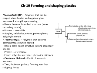
Two Types of Plastics 1. Thermoplastics • Chemical structure remains unchanged during heating and shaping • More important commercially, comprising more than 70% of total plastics tonnage • Thermosets • Undergo a curing process during heating and shaping, causing a permanent change (cross‑linking) in molecular structure • Once cured, they cannot be remelted
Polymer Melts • To shape a thermoplastic polymer it must be heated so that it softens to the consistency of a liquid • In this form, it is called a polymer melt • Important properties of polymer melts: • Viscosity • Viscoelasticity
Viscosity of Polymer Melts Fluid property that relates shear stress to shear rate during flow • Due to its high molecular weight, a polymer melt is a fluid with high viscosity • Most polymer shaping processes involve flow through small channels or die openings • Flow rates are often large, leading to high shear rates and shear stresses, so significant pressures are required to accomplish the processes
Viscosity of a polymer melt decreases with shear rate, thus the fluid becomes thinner at higher shear rates Figure 13.1 Viscosity relationships for Newtonian fluid and typical polymer melt. Viscosity and Shear Rate
Viscosity and Temperature Viscosity decreases with temperature, thus the fluid becomes thinner at higher temperatures Figure 13.2 Viscosity as a function of temperature for selected polymers at a shear rate of 103 s-1.
Viscoelasticity Combination of viscosity and elasticity • Possessed by both polymer solids and polymer melts • Example: die swell in extrusion, in which the hot plastic expands when exiting the die opening
Die Swell Extruded polymer "remembers" its previous shape when in the larger cross section of the extruder, tries to return to it after leaving the die orifice Figure 13.3 Die swell, a manifestation of viscoelasticity in polymer melts, as depicted here on exiting an extrusion die.
Extrusion Compression process in which material is forced to flow through a die orifice to provide long continuous product whose cross‑sectional shape is determined by the shape of the orifice • Widely used for thermoplastics and elastomers to mass produce items such as tubing, pipes, hose, structural shapes, sheet and film, continuous filaments, and coated electrical wire • Carried out as a continuous process; extrudate is then cut into desired lengths
Extruder Figure 13.4 Components and features of a (single‑screw) extruder for plastics and elastomers
Extruder Screw • Divided into sections to serve several functions: • Feed section - feedstock is moved from hopper and preheated • Compression section - polymer is transformed into fluid, air mixed with pellets is extracted from melt, and material is compressed • Metering section - melt is homogenized and sufficient pressure developed to pump it through die opening
Die End of Extruder • Progress of polymer melt through barrel leads ultimately to the die zone • Before reaching die, the melt passes through a screen pack - series of wire meshes supported by a stiff plate containing small axial holes • Functions of screen pack: • Filter out contaminants and hard lumps • Build pressure in metering section • Straighten flow of polymer melt and remove its "memory" of circular motion from screw
Die Configurations and Extruded Products • The shape of the die orifice determines the cross‑sectional shape of the extrudate • Common die profiles and corresponding extruded shapes: • Solid profiles • Hollow profiles, such as tubes • Wire and cable coating • Sheet and film • Filaments
Extrusion of Solid Profiles • Regular shapes such as • Rounds • Squares • Irregular cross sections such as • Structural shapes • Door and window moldings • Automobile trim • House siding
Extrusion Die for Solid Cross Section Figure : (a) Side view cross‑section of an extrusion die for solid regular shapes, such as round stock; (b) front view of die, with profile of extrudate.
Hollow Profiles • Examples: tubes, pipes, hoses, and other cross‑sections containing holes • Hollow profiles require mandrel to form the shape • Mandrel held in place using a spider • Polymer melt flows around legs supporting the mandrel to reunite into a monolithic tube wall • Mandrel often includes an air channel through which air is blown to maintain hollow form of extrudate during hardening
Extrusion Die for Hollow Shapes Figure 13.10 Side view cross‑section of extrusion die for shaping hollow cross‑sections such as tubes and pipes; Section A‑A is a front view cross‑section showing how the mandrel is held in place; Section B‑B shows the tubular cross‑section just prior to exiting the die; die swell causes an enlargement of the diameter.
Wire and Cable Coating • Polymer melt is applied to bare wire as it is pulled at high speed through a die • A slight vacuum is drawn between wire and polymer to promote adhesion of coating • Wire provides rigidity during cooling - usually aided by passing coated wire through a water trough • Product is wound onto large spools at speeds up to 50 m/s (10,000 ft/min)
Extrusion Die for Coating Wire Figure : Side view cross‑section of die for coating of electrical wire by extrusion.
Polymer Sheet and Film • Film - thickness below 0.5 mm (0.020 in.) • Packaging - product wrapping material, grocery bags, and garbage bags • Stock for photographic film • Pool covers and liners for irrigation ditches • Sheet - thickness from 0.5 mm (0.020 in.) to about 12.5 mm (0.5 in.) • Flat window glazing • Thermoforming stock
Sheet and Film Production Processes • Most widely used processes are continuous, high production operations • Processes include: • Slit‑Die Extrusion of Sheet and Film • Blown‑Film Extrusion Process • Calendering
Slit‑Die Extrusion of Sheet and Film Production of sheet and film by conventional extrusion, using a narrow slit as the die opening • Slit may be up to 3 m (10 ft) wide and as narrow as around 0.4 mm (0.015 in) • A problem is uniformity of thickness throughout width of stock, due to drastic shape change of polymer melt as it flows through die • Edges of film usually must be trimmed because of thickening at edges
Slit Die Extrusion Figure 13.14 One of several die configurations for extruding sheet and film.
Blown‑Film Extrusion Process Combines extrusion and blowing to produce thin- film tubes, plastic bags • Process sequence: • Extrusion of tube • Tube is drawn upward while still molten and simultaneously expanded by air inflated into it through die • Air is blown into tube to maintain uniform film thickness and tube diameter
Blown-film Process Figure 13.16 Blown‑film process for high production of thin tubular film.
Calendering Feedstock is passed through a series of rolls to reduce thickness to desired gage • Expensive equipment, high production rates • Process is noted for good surface finish and high gage accuracy • Typical materials: rubber or rubbery thermoplastics such as plasticized PVC • Products: PVC floor covering, shower curtains, vinyl table cloths, pool liners, and inflatable boats and toys
Calendering Figure 13.17 A typical roll configuration in calendering
Fiber and Filament Products • Definitions: • Fiber - a long, thin strand whose length is at least 100 times its cross‑section • Filament - a fiber of continuous length • Applications: • Fibers and filaments for textiles • Most important application • Reinforcing materials in polymer composites • Growing application, but still small compared to textiles
Materials for Fibers and Filaments Fibers can be natural or synthetic • Natural fibers constitute ~ 25% of total market • Cotton is by far the most important staple • Wool production is significantly less than cotton • Synthetic fibers constitute ~ 75% of total fiber market • Polyester is the most important • Others: nylon, acrylics, and rayon
Fiber and Filament Production - Spinning For synthetic fibers, spinning = extrusion of polymer melt or solution through a spinneret, then drawing and winding onto a bobbin • Spinneret = die with multiple small holes • The term is a holdover from methods used to draw and twist natural fibers into yarn or thread
Melt Spinning Starting polymer is heated to molten state and pumped through spinneret • Typical spinneret is 6 mm (0.25 in) thick and contains approximately 50 holes of diameter 0.25 mm (0.010 in) • Filaments are drawn and air cooled before being spooled onto bobbin • Significant extension and thinning of filaments occur while polymer is still molten, so final diameter wound onto bobbin may be only 1/10 of extruded size • Used for polyester and nylonfilaments
Melt Spinning Figure 13.18 Melt spinning of continuous filaments
Injection Molding Polymer is heated to a highly plastic state and forced to flow under high pressure into a mold cavity where it solidifies and the molding is then removed from cavity • Produces discrete components almost always to net shape • Typical cycle time 10 to 30 sec, but cycles of one minute or more are not uncommon • Mold may contain multiple cavities, so multiple moldings are produced each cycle
Injection Molded Parts • Complex and intricate shapes are possible • Shape limitations: • Capability to fabricate a mold whose cavity is the same geometry as part • Shape must allow for part removal from mold • Part size from 50 g (2 oz) up to 25 kg (more than 50 lb), e.g., automobile bumpers • Injection molding is economical only for large production quantities due to high cost of mold
Polymers for Injection Molding • Injection molding is the most widely used molding process for thermoplastics • Some thermosets and elastomers are injection molded • Modifications in equipment and operating parameters must be made to avoid premature cross‑linking of these materials before injection
Injection Molding Machine Two principal components: • Injection unit • Melts and delivers polymer melt • Operates much like an extruder • Clamping unit • Opens and closes mold each injection cycle
Injection Molding Machine Figure 13.20 A large (3000 ton capacity) injection molding machine (Photo courtesy of Cincinnati Milacron).
Injection Molding Machine Figure 13.21 Diagram of an injection molding machine, reciprocating screw type (some mechanical details are simplified).
Injection Molding Cycle Figure 13.22 Typical molding cycle: (1) mold is closed
Injection Molding Cycle Figure 13.22 Typical molding cycle: (2) melt is injected into cavity.
Injection Molding Cycle Figure 13.22 Typical molding cycle: (3) screw is retracted.
Injection Molding Cycle Figure 13.22 Typical molding cycle: (4) mold opens and part is ejected.
The Mold • The special tool in injection molding • Custom‑designed and fabricated for the part to be produced • When production run is finished, the mold is replaced with a new mold for the next part • Various types of mold for injection molding: • Cold-runner two-plate mold • Cold-runner three-plate mold • Hot-runner mold
Cold-Runner Two-Plate Mold Figure 13.23 Details of a two‑plate mold for thermoplastic injection molding: (a) closed. Mold has two cavities to produce two cup‑shaped parts with each injection shot.
Cold-Runner Two-Plate Mold Figure 13.23 Details of a two‑plate mold for thermoplastic injection molding: (b) open
Cold-Runner Two‑Plate Mold Features • Cavity – geometry of part but slightly oversized to allow for shrinkage • Created by machining of mating surfaces of two mold halves • Distribution channel through which polymer melt flows from nozzle into mold cavity • Sprue - leads from nozzle into mold • Runners - lead from sprue to cavity (or cavities) • Gates - constrict flow of plastic into cavity