Download
1 / 27
270 likes | 271 Views
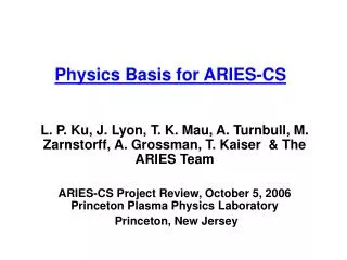
Physics Basis for ARIES-CS. L. P. Ku, J. Lyon, T. K. Mau, A. Turnbull, M. Zarnstorff, A. Grossman, T. Kaiser & The ARIES Team ARIES-CS Project Review, October 5, 2006 Princeton Plasma Physics Laboratory Princeton, New Jersey. Outline of Discussions.

E N D
Physics Basis for ARIES-CS L. P. Ku, J. Lyon, T. K. Mau, A. Turnbull, M. Zarnstorff, A. Grossman, T. Kaiser & The ARIES Team ARIES-CS Project Review, October 5, 2006 Princeton Plasma Physics Laboratory Princeton, New Jersey
Outline of Discussions • Physics basis for the baseline configuration • Unique features • Equilibrium and MHD stability • Transport and confinement • Coils • Magnetic topology outside LCMS • Basis for configuration design approach • Critical considerations in QA reactors • Configuration optimization • Advanced configurations • Family in which the baseline configuration is a member • Extra-low aspect ratio • High rotational transforms • Connection to NCSX • Summary/Conclusions
The Baseline Configuration The baseline plasma is a three field-period, aspect ratio 4.5, quasi-axisymmtric configuration with R=7.75 m. Reference parameters for baseline: R=7.75 m, <a>=1.72 m, <n>=3.6·1020 m-3, <T>=5.73 keV, B=5.7 T, b=5%, P(fusion)= 2.364 GW P(electric)= 1 GW Plane and perspective view of the geometry and |B| of the last closed magnetic surface J. Lyon, this meeting
The configuration has “good” quasi-axisymmetry, but it also has a “not so small” amount of mirror (B1,0) and its side-band helical (B1,1) component. The “residues” are specifically introduced to improve confinement of fast ions. |B| in u-v space on surfaces at r/a~0.5, 0.7 and 1.0 Collisionless orbits improved with ~1-2% B(0,1) as seen in an earlier study. N3AEC, toroidal transit limit=500, R=10 m, B=5.5 T, a born on r/a=0.5.
The 1-2% mirror field helps modify ripple distribution along field lines to reduce the overall B drift loss* without compromising the equilibrium and MHD stability properties. Noise 1.8% 3.5% r/a~0.5 B(0,1) r/a~0.7 *H. Mynick, A. Boozer and L. P. Ku, to appear in Phys. Plasmas
The plasma may be described by* where D2,0=-0.25, D2,1=-0.41, D3,0=0.14, D-1,0=0.11, D3,1=0.15, D-1,-1=0.17, D0,1=0.07, D3,2=0.06, D4,0=-0.06, with D0,0 =1. k~1.7, d~0.7 D0,1=0.04 for NCSX Plasma cross section seen in four equally spaced toroidal angles. *L. P. Ku & P. Garabedian, FS&T, 50, 207 (2006)
The baseline equilibrium is calculated assuming a peaked pressure profile and shifted current profile derived from ARIES-RS studies to assure favorable MHD stability. A hollow density profile is assumed in the systems code and also in some a slowing down calculations with the temperature profile chosen to provide a consistent pressure profile. Sensitivities of MHD stability and particle transport to different profiles have been examined in a limited number of cases*. In these cases, most favorable characteristics remain unchanged. Temperature p{1-(r/a)2.1}1.21 Density p(peak)/p(average)~2.1
<< 1/2 Equilibrium calculations indicate small Shafranov shifts at high b thanks to the significant transform from plasma shaping and the small plasma aspect ratio. The rotational transform increases nearly monotonically as the plasma radius increases. Equilibrium calculated @ 5% b by VMEC* External and finite b total transform *VMEC—S. P. Hirshman, W. I. van Rij, P. Merkel, Comp. Phys. Commun. 43, 143 (1986)
Fixed-boundary equilibrium calculation without presupposition of the existence of nested flux surfaces indicates the configuration has good surface integrity. Islands do exist but the widths are small and so is the potential loss of fluxes. Poincaré plot of an equilibrium at 5% b by PIES* *PIES– A. Reiman and H. Greenside, Comp. Phys. Commun. 43, 157 (1986) **L.P. Ku, ARIES-CS project meeting presentation, Princeton, Dec 3 (2003). Also, San Diego, Jan 23 (2006).
The configuration is stable to the vertical mode (1,0) as i(ext)/i75%. The configuration is also stable to the external kink modes at ~5% b without passive stabilization (Terpsichore* calculations). • Terpsichore stability calculations with conformal wall at twice plasma radius**: • 197 radial flux surfaces • Up to 101 toroidal-poloidal mode combinations • Varying at constant : • Reference case = 4.06%: Marginal unstable () • 9/6 (10/6 5/3) peaked at edge and • 6/4 3/2 7/4 2/1 10/7 peaked at edge • Decreasing = 3.24%, 2.01% at constant is weakly destabilizing • Increasing = 4.88%, 6.13%, 8.22% at constant is stabilizing: • Stable still at 8.22% for this profile • Interpreted as a weakly unstable current driven mode • Otherwise, robustly stable • Varying profile at constant : • b = 0.698: Unstable 3/2 7/5 6/4 8/5 4/2 peaked at edge ( • b = 0.599: Marginal unstable 13/5 14/5 12/5 11/5 peaked in core ( • b = 0.732: Unstable 3/2 7/5 1/1 4/2 8/5 peaked at edge ( HSR: ~3.5% for global modes. *Terpsichore—D. V. Anderson, W. A. Cooper, R. Gruber, S. Merazzi and U. Schwenn, Sci. Comput. Supercomput. II, 159 (1990). **A. Turnbull, ARIES-CS project meeting presentation, Princeton, Oct 4 (2006).
When a broader current profile is used in sensitivity studies, a small modification of the plasma shape will suffice to re-stabilize the kink modes at 5% b, indicating the configuration has favorable characteristics for global mode stability. Current Density kink stable using the reference J profile. kink stable at 5% b using a broad J profile.
Infinite-n Ballooning The configuration has good stability characteristics to the Mercier and ballooning modes (COBRA* calculations). unstable unstable FLR correction typically leads to a higher ballooning b limit (~50%). Local pressure flattening also leads to higher limits. b=3, 4, 5, 6% b=3, 4, 5, 6% stable stable *COBRA—R. Sanchez, S. P. Hirshman, J. C. Whitson, A. Ware, J. Comput. Phys., 161, 589 (2000)
Recent W7AS and LHD Experiments: Steady High-b, Above Linear Limit. (courtesy of M. Zarnstorff) Germany PPPL & MP/IPP Collaboration Japan • In both cases, well above theoretical stability limit < 2% • Not limited by MHD activity. No disruptions observed. Sustained without CD.
The configuration has very low effective ripple, being everywhere < 0.5%, despite the existence of 1-2% of B(0,1) and B(1,1). e-eff calculated by NEO* Anomalous transport is expected to dominate the thermal loss. Power balance will be achieved without auxiliary heating if the energy confinement (~1 s) follows the ISS-95 scaling with H~1.5 (J Lyon, this meeting). HSR-18: <0.6% FFHR; ~10% ISS04 has a more favorable scaling. ~20 MW auxiliary power is required during startup to reach ignition. Paths of startup have not been studied. NEO—V. V. Nemov, S. V. Kasilov, W. Kernbichler and M. F. Heyn, Phys. Plasma, 6(12), 4622 (1999)
Alpha loss scales approximately with R2 and B2 and also scales with collisionality.The density at operating temperature is chosen to provide high collisionality subject to the constraint of Sudo density limit such that the energy loss fraction of alphas is limited to ~5%. R=7 m B=6.5 T, 5% b R=10 m HSR-18: ~2.5% FFHR: ~10% Footprint of lost a in (q,f), lost particle energy distribution and cumulative particle loss versus time for the baseline configuration (ORBIT3D* calculations). *ORBIT3D—R. B. White and M. S. Chance, Phys. fluids, 27, 2455 (1984)
Modular and PF coils are designed following the NCSX design principles but are optimized to minimize the coil aspect ratio. Courtesy of Xueren Wang Modular coil winding pack: 0.194 m x 0.743 m I(max)~13.5 MA, B(max)~15 T, R/D(C-P)~5.9, R/D(C-C)~10. PF coils are designed for startup and equilibrium position control. I(max)< 5 MA. HSR: 10 T (NbTi) FFHR: 13 T
Field topology outside LCMS is similar to that of NCSX with a natural flux expansion at tips of the crescent shaped section. Divertor plates are designed in this region by allowing sufficiently long connection lengths for the field lines, maximizing field line intersections with plates and minimizing the heat load peaking factor. plate/baffle area <15% A(1st wall) peak heat load ≤ 10 MW/m2 0 30 Poincare plots for solutions obtained by MFBE/GOURDON*. E. Strumberger, Nucl. Fusion 37, 19, 1997.
An initial divertor design with 0.2 m offset from LCMS and with 25 toroidal 20 poloidal extension, respectively, shows that the plates provide ~85% field line intersection and an average connection length ~250 m*, leading to adequate up-stream to target temperature separations (>300 eV) at high separatrix densities (~5·1019 m-3) and good radiated power fraction in SOL and divertors (>50%)**. ~11 *T. K. Mau, ARIES-CS project meeting presentation, Oct 4 (2006).**Self-consistent edge modeling has not yet been studied in detail. A brief study was done by J. Lyon and R. Maingi using the Borrass model. Power flow – J. Lyon (this meeting), Thermomechanical – R. Raffray (this meeting). ~2% fusion power deposited on divertors as conductive/convective processes.
FFHR-2 Basis for Configuration Design Approachmotivation and goals Lower COE L.P. Ku, ARIES-CS project meeting presentation, San Diego, Nov 4-5 (2004). • Compact reactor system QAS, QPS QHS? Courtesy of J. Lyon HSR: <j||>/<j> FFHR:D(c-p)
Important Issues and Configuration Optimization • Critical considerations for QA reactors ( in addition to MHD stability and thermal confinement for experimental QA devices) • Confinement of a, • flux surface integrity, • space for blanket/shielding, • maximum field in superconductors, • coils for ease of machine maintenance • HSR: low PS and BS, quasi-idodynamicity for a confinement, flux surface, B(max) in coils, space for blanket/shielding • FFHR: B(max) in coils, space for blanket, long-life components • Tokamaks: P(recirculation) for CD and alignment of J for MHD stability, vertical stability and feedback control, kink stability and stabilizing shell
Configuration development is a non-linear, constrained mathematical optimization problem, one that is to maximize the symmetry property subject to additional constraints by varying the shape of the LCMS. • In QAS, bootstrap currents may drive the kink instability • Pressure may drive ballooning and other interchange instabilities • Pressure may enhance the effects of resonance perturbation • Engineering constraints for blanket/shielding and coils • Consideration given in the development of baseline configuration • Using limited Fourier modes in describing plasma boundary m≤6, n≤4 • Rotational transform due to external coils 50% • MHD stability to Mercier/ballooning/kinks ~ 4-5% b using the ideal, linear theory (vary plasma shape but not the pressure profile) • Effective ripple ≤1%, a energy loss ≤10% • Coil aspect ratio ≤6, separation ratio ≤12 Important, but not included: (1) minimizing resonance perturbation, (2) optimizing pressure profile for both minimizing the peaking of neutron wall load and maximizing MHD stability, (3) optimizing first wall shape to minimize heat load variations, (4) maximizing maintenance port size in coil design, (5) minimizing B peaking in coils.
We build upon previous design studies: • NCSX • Minimizing a loss, reduce e-eff • MHH2/3/4 • Reduce A, design coils for finite b (P. Garabedian) • We broaden the search of the configuration landscape, leading to the discovery of many additional interesting configurations. • Generalized baseline configuration family • “Ultra-low” plasma aspect ratio QAS with “low” coil aspect ratio coils comparable to tokamak reactors • Configurations with carefully tailored rotational transforms.
A=3.5 A=4.0 A=4.5 A=5.0 A=5.6 The Advanced and Other Interesting Configurations The baseline configuration is a member of the family having the characteristic mirror and helical components in the magnetic spectrum. Configurations in this family spans a wide range of aspect ratios and rotational transforms. i~0.15 per field period A~1.9 per period A~1.2 per period B(0,1)/B(0,0)~0% B(0,1)/B(0,0)~4% i~0.21 per field period
It appears that the lower end of the aspect ratio to maintain good quasi-axisymmetry is ~1.2 per field period, leading to the possibility of designing configurations with A as small as 2.5 for two field-period machines. Here is an example of the MHH2 family (MHH2-K14) chosen for its “gentle” shape. MHD stability and flux surface quality need more studies. r/a~0.7 R/Dmin(coil-plasma)~5.5 *P. Garabedian & L. P. Ku, FS&T, 47, 400 (2005) *L. P. Ku, Proc. 21st IEEE/NPSS Symposium on Fusion Engineering, Knoxville, TN, Sept. 26-29 (2005).
We have also developed the “SNS” family of configurations whose rotational transform profiles are specifically designed to minimize the effects of resonance on the surface integrity. There are members in the family of the baseline configuration that also have similar properties. Here is an example with A~4.5 in which the iota profile lies in a region without low order resonances at 5% b*. Coils with good physics and engineering properties need to be designed. Equilibrium at 5% b calcuated by the PIES code, showing the excellent flux surface integrity i~2.1/period L.P. Ku, ARIES-CS project meeting presentation, San Diego, June 14 (2006).
NCSX experiment will provide necessary physics data base for design improvement. • Design involves tradeoffs. Experimental data will help to quantify (courtesy of M. Zarnstorff): • Rotational transform from coils and self-generated bootstrap current (how much of each?) • bootstrap current affected by levels of non-axisymmetric residues (how sensitive?) • 3D plasma shaping to stabilize instabilities (how strong?) • Quasi-axisymmetry to reduce ripple transport, alpha losses, flow damping (how low must ripple be?) • Role of non-axisymmetric residues in ripple transport (good/bad? which one? how much?) • Power and particle exhaust via a divertor (what topology?) • R/a (how low?) and (how high?)
Summary and Conclusion • The baseline configuration meets requirements of MHD stability and particle confinement necessary for high b operations. Divertors have been designed for particle and power handling. • The baseline coils have sufficient space for blanket/shielding so that reactors of R≤8 m to yield 1 GW electric power is achievable. Coil to coil spacing is also sufficient for the implementation of port maintenance scheme. • Our efforts have revealed a rich landscape for QA configurations. Still better reactor designs may be found when given more efforts to improve coil designs and system trade-offs. • The experimental results of NCSX should provide a physics data base using which the uncertainties of the present day design will be reduced and improved design criteria established.