Download
1 / 37
370 likes | 467 Views
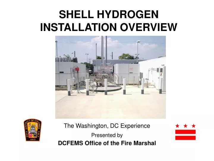
SHELL HYDROGEN INSTALLATION OVERVIEW. The Washington, DC Experience Presented by DCFEMS Office of the Fire Marshal. Presentation Overview.

E N D
SHELL HYDROGEN INSTALLATION OVERVIEW The Washington, DC Experience Presented by DCFEMS Office of the Fire Marshal
Presentation Overview • The liquid and gaseous hydrogen fueling system located on the site at 3355 Benning Road NE is one that came with a few challenges that had to be satisfied before the DCFEMS Office of the Fire Marshal could grant its installation and approval. • This presentation is intended to explore these challenges and briefly explain how they where overcome. DC Office ofthe Fire Marshal
Key Reasoning • First and foremost, it’s important to state the key reasoning behind allowing the entire system installation. • Primarily, it was due to the fact that city construction codes are not intended to prevent the use of any alternate material, equipment or method of construction and welcomes innovative changes due to technological advances. DC Office ofthe Fire Marshal
Codes and Reference Standards Used The approval and instillation of the Shell Hydrogen fueling system required the following codes and reference standards to be carefully reviewed and used as guides during the pre-planning process: • International Fire Code- 2000 edition • International Building Code- 2000 edition • DCMR Title 20, Chapter’s 55-70-Environmental Law Requirements for Fuel Storage Tanks DC Office ofthe Fire Marshal
Codes and Reference Standards Used • NFPA 30- Flammable and Combustible Liquids Standard • NFPA 30- Motor Fuel Dispensing Facilities Standard • NFPA 50A- Standard for Gaseous Hydrogen Systems at Consumer Sites • NFPA 50B- Standard for Liquid Hydrogen Systems at Consumer Sites • NFPA 52- Compressed Natural Gas (CNG) Vehicular Fueling System Standard DC Office ofthe Fire Marshal
Codes and Reference Standards Used • NFPA 57- Liquefied Natural Gas (LNG) Vehicular Fueling System Standard • NFPA 59A- Standard for the Production, Storage, and Handling of Liquefied Natural Gas • NFPA 70- National Electric Code • ASME BPV Code, Section VIII, Division I- Rules for Construction of Pressure vessels • ASME BPV Code, Section IX- Welding and Brazing Qualifications • ASME/ ANSI B31.3- Piping Design Standards DC Office ofthe Fire Marshal
Our Research Findings • Our investigation and research showed that the technical challenges of a below grade hydrogen tank could possibly be overcame as it related to the regulatory process. • Though current codes and standards did not discuss the use of hydrogen tanks below grade, we found that standards such as NFPA 57 and NFPA 59A did provide adequate requirements for the underground storage or liquefied natural gas (LNG). • We immediately recognized that Liquefied natural gas (LNG) is very similar to liquid hydrogen in that both are cryogenic, flammable, refrigerated gases. DC Office ofthe Fire Marshal
Our Research Findings • Taking the site location into consideration, DC Fire Marshal representatives agreed that the primary safety advantage of this below grade liquid hydrogen tank is its inability to be involved in an engulfing fire. • Meaning, the earth around the tank serves to shield the tank from the tremendous heat flux of a hydrocarbon fire. • A heat flux that could cause structural issues as well as provide a source of overpressure to the cryogenic vessel as its contents expand. DC Office ofthe Fire Marshal
Our Research Findings • Secondary benefits include protection from external impact as well as presenting less of a target from illegal activities. • However, out of these benefits came one large challenge, tank vessel corrosion and possible product loss due to corrosion caused by the direct burial and earth contact over time. DC Office ofthe Fire Marshal
The Tank and Solution • The hydrogen storage tank located at the Benning Road fueling facility is designed to hold 1500 gallons of liquid hydrogen at a 60 psig operating pressure, but is rated for a maximum average working pressure (MAWP) of 90psig. • It is vacuum jacketed to prevent the loss of product. Both the inner and outer linings are constructed of stainless steel, which are both housed in a fiberglass outer liner system to protect the tank from corrosion that is normally associated with direct tank burials. • Basically, this fiberglass liner system serves as a vault-like area by totally encapsulating the actual pressurized vessel preventing any soil or earth contact with the double lined tank inside. DC Office ofthe Fire Marshal
Original Proposed Tank Design No Outer Fiberglass Tank Enclosure Direct Burial Double Wall Stainless steel Tank/ Vessel DC Office ofthe Fire Marshal
Final Tank Design Illustration Double Wall Steel Inner Tank/ Vessel Fiberglass Out Tank Housing No Direct Earth Contact for the Steel Tank/ Vessel No Corrosion Concerns Concrete Pad DC Office ofthe Fire Marshal
The Tank Safety Components • The standard tank is equipped with a pressure build circuit, a safety circuit, level and pressure indicators, and all the necessary piping and valves required to fill and withdraw liquid hydrogen product. • The tank is equipped with an automatic venting feature to prevent the operation of the safety relief valves unless it is necessary. • When the pressure in the tank reaches 90% of its maximum average working pressure (MAWP), which is approximately 80 psig, the control system opens the automatic vent valve, venting the excess pressure through the tank’s vent stack. DC Office ofthe Fire Marshal
The Tank Safety Components The hydrogen tank is also equipped with some added safety features due to the low minimum ignition energy needed for flammable mixtures containing hydrogen. These safety features are as follows: • All vent lines, safety valves, and rupture disk are piped to the vent stack. The primary vent stack on this hydrogen tank system is located 25’ above ground and near by equipment as required by current gases group standards. DC Office ofthe Fire Marshal
The Tank Safety Components • The liquid withdrawal line is equipped with an air-operated valve, which also serves as the fire control valve. The valve is fail-closed air to open. The instrument airline is installed with a fusible link near the valve. The fusible link is designed to melt in a fire, which will vent the air supply and close the valve. • The air supply is also vented if the control panel detects that an emergency stop button is engaged. The emergency stop buttons are located within 25’ of the system. • The majority of the piping (85%) affiliated with the tank is welded because hydrogen can readily migrate through small openings and torturous paths. DC Office ofthe Fire Marshal
Dispensing Capabilities In addition to the hydrogen tank itself, the system is also comprised of the following components that enable hydrogen to be dispensed in a gaseous state at 5,000 and 10,000 psig and a liquid state at 55 psig. Liquid Process, 55 psig: • Liquid hydrogen is pumped from the 1,500 gallon below grade hydrogen storage tank, with a 60 psig operating pressure through an underground piping system to an electronic fuel dispenser for dispensing at 55 psig through the filling nozzle. DC Office ofthe Fire Marshal
Gaseous Process 5,000 psig • A three-stage (3) compressor that is designed to receive hydrogen from the liquid hydrogen tank vessel’s gaseous conversion system located directly above the storage tank at an inlet pressure of 60 psig, where it is increased to and discharged at an outlet pressure of 5,500 psig. • 24 Insulated, vacuum-jacketed ASME cylinders store the compressed gaseous hydrogen at 5,500 psig when received from the three-stage compressor. These cylinders have a maximum average working pressure (MAWP) rated at 7,000 psig. At this stage, the gaseous hydrogen can be dispensed from these cylinders via a piping system to an electronic dual pressure, dual hose fuel dispenser at 350 bar. DC Office ofthe Fire Marshal
Gaseous Process, 10,000 psig • A three-stage (3) compressor that is designed to receive hydrogen from the liquid hydrogen tank vessel’s gaseous conversion system located directly above the storage tank at an inlet pressure of 60 psig, where it is increased to and discharged at an outlet pressure of 5,500 psig. • 24 Insulated, vacuum-jacketed ASME cylinders store the compressed gaseous hydrogen at 5,500 psig when received from the three-stage compressor. These cylinders have a maximum average working pressure (MAWP) rated at 7,000 psig. DC Office ofthe Fire Marshal
Gaseous Process, 10,000 psig • A single-stage buster compressor that receives the gaseous hydrogen at 5,500 psig from the 24 storage cylinders mentioned above, where its pressure is increased to and discharged at an outlet pressure of 11,000 psig. • The hydrogen is passed to three (3) Insulated vacuum-jacketed ASME cylinders that store the compressed gaseous product at 10,000 psig when it is received from the one-stage compressor. These cylinders have a maximum average working pressure (MAWP) rated at 11,000 psig. At this stage, the gaseous hydrogen can be dispensed from these cylinders via a piping system to an electronic, dual pressure, dual hose fuel dispenser at 700 bar. DC Office ofthe Fire Marshal
A Closer Look AtSystem Components Cascading tank gauge reads 5,500 psi Three stage compressor 5,500-psi output DC Office ofthe Fire Marshal
A Closer Look AtSystem Components Stored compressed gas cylinders (Front view) 24 Cylinders store compressed gas at 5,500 psi Vacuum-jacketed ASME Certified DC Office ofthe Fire Marshal
A Closer Look AtSystem Components Hydrogen system filling point (Inlet 60 psi) 3 Cylinders store compressed gas at 10,000 psi Vacuum-jacketed ASME Certified DC Office ofthe Fire Marshal
A Closer Look AtSystem Components Duel Gaseous Dispenser (5,000 and 10,000 psi) Liquid Dispenser (Straight from tank) DC Office ofthe Fire Marshal
A Closer Look AtSystem Components Liquid Dispenser Nozzle (55 psig) Emergency shut off located 25’ from system DC Office ofthe Fire Marshal
A Closer Look AtSystem Components Conversion System (above below grade tank) Wide view of entire system and components DC Office ofthe Fire Marshal
A Closer Look AtSystem Components System Pressure Valves and Gauges Hydrogen Tank Bolted Cover Lid Device DC Office ofthe Fire Marshal
A Closer Look AtSystem Components Another System Shut Off (at system fill point) System Vent Stacks (12’ and 25’ high) DC Office ofthe Fire Marshal
A Closer Look AtSystem Components Infrared Hydrogen Gas/ Flame Detectors Hydrogen Gas Detectors located at various Points On System DC Office ofthe Fire Marshal
The Site and Location • The site selection for the hydrogen system is one that posed a few concerns initially, but they were soon over come in the code research process. The system was incorporated into an existing Texaco station that housed six fuel-dispensing islands. One of the islands was converted to house the liquid hydrogen fuel dispenser. • Specifically, the hydrogen tank storage area (below grade) is located on the right rear side of the service station property along with the gaseous hydrogen dispenser, approximately 50 feet from the property line and 85 feet from the gasoline tank farm storage area. DC Office ofthe Fire Marshal
The Site and Location • The overall location sets directly off of a main throughway (Benning Road) surrounded by a body water to the right side (Anacostia River), a residential community to the rear (River Terrace), and a main interstate to the left (I295). • An initial concern from the perspective of the Fire Marshal’s Office was the location being so close to the residential community, body of water, and the electric power plant (PEPCO) on the other side of the highway. DC Office ofthe Fire Marshal
The Site and Location • The concerns were soon eased because of the design of the tank itself and distance requirements set forth in NFPA. Most of the NFPA requirements were set at 50 feet from structures and important building surrounding the hydrogen storage. • The residential community set more than 200 feet from the property line of the service station and the river is located more that 500 feet from the same. DC Office ofthe Fire Marshal
The Site and Location • The issue with the power plant was purely based on the amount of electrolysis that could produce in the ground area, even though the facility sets more than 1,000 feet across the highway. • The design of the tank incorporated a fiberglass outer protected lining system, which cured this concern. DC Office ofthe Fire Marshal
What did DCFEMS Do After Hydrogen System Installation? Established Emergency Response Procedures hydrogen related incidents and introduced system to all departmental first responders by conducting on-site walk visits and demonstrations in conjunction with Shell Hydrogen representatives. DC Office ofthe Fire Marshal
DCFEMS Recommendations • Get the affected community involved on the front end of the project proposal. • Conduct community awareness meetings in the affected area with representatives from the jurisdictional authorities (Fire, Environmental, Zoning, and Regulatory affairs Offices) including the hydrogen company representatives (Shell, etc). Remember residents have a voice! DC Office ofthe Fire Marshal
DCFEMS Recommendations • Develop Hydrogen educational programs in partnership with the community leaders and the hydrogen users (company). • Discuss all safety operational procedures with company and community and ensure that they are strictly enforce through the code enforcement process. • Develop and discuss community emergency evacuation procedures. (Evacuation route etc.) Always be truthful to the community! DC Office ofthe Fire Marshal
QUESTIONS DC Office ofthe Fire Marshal