Download
1 / 51
510 likes | 678 Views
Use of Simulated Annealing in Quantum Circuit Synthesis. Manoj Rajagopalan 17 Jun 2002. Outline. Overview Simulated Annealing: the idea used Implementation Results Conclusions and Future Work. Quantum Circuit Synthesis. Input-output transformation specified

E N D
Use of Simulated Annealing in Quantum Circuit Synthesis Manoj Rajagopalan 17 Jun 2002
Outline • Overview • Simulated Annealing: the idea used • Implementation • Results • Conclusions and Future Work
Quantum Circuit Synthesis • Input-output transformation specified • Objective: Gates and their arrangement into a circuit to achieve this transformation • Methods: • Factorization <vshende> (Cybenko) • Enumeration <gmathew, akprasad> (exhaustive, B&B) • Genetic Algorithms <smaddipa> (Williams+, Yabuki+) • Simulated Annealing <rmanoj> ( )
Synthesis by SA • Choose whole circuit every time • Use equivalent transformations (optimization) • Incremental modification (ends of circuit) • Computationally efficient! • But is it good enough? • Hey, what is Simulated Annealing?
Optimization Problems • State variables: • Reflect the system state • May not be directly modified • Control variables (degrees of freedom): • Affect the state • Directly modified • Constraints on state and control (equality/inequality) • Objective: Solve for optimum of scalar objective function
Optimization Heuristics • Search space is too large for exhaustive enumeration, too complex to visualize • Pick random solutions and evaluate performance index (PI) • Filter good/best solution(s) • Perturb these and re-evaluate PI • Incorporate means to avoid local minima
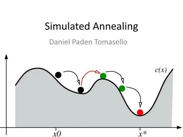
Simulated Annealing: Basic Idea • Objective: minimize scalar function subject to given constraints • Select one initial solution and evaluate cost • Perturb the solution and calculate new cost • Improvement in cost? • Yes: Copy perturbed solution to initial solution • No: Probabilistically accept perturbed solution (to avoid local minima)
Quantum Circuit Synthesis as an Optimization Problem • Select type, number and location of gates (control) • Evaluate equivalent unitary operator (state) • Constraint: Operator == given unitary • Objective: Minimize number of gates
Outline • Overview • Simulated Annealing: the idea used • Incremental perturbation • Implementation • Results • Conclusions and Future Work
SA: Quantum Circuit Synthesis • Assume given operator can be synthesized • Number of qubits known for given operator • Choose entire circuits in each perturbation? • How many gates? • What location? • Need to ‘multiply’ all gates to get equivalent operator each time! • Alternative: Incremental modification (at ends of circuit each time): NOP, ADD, REM, REP • Qubits handled independently
SA: Incremental Perturbation H S #0 H #1 H T #2 #3 ADD: Hadamard Gate to #1
SA: Incremental Perturbation H S #0 H H #1 H T #2 #3 ADD: Hadamard Gate to #1
SA: Incremental Perturbation • Equivalent Operator =
SA: Incremental Perturbation H S #0 H #1 H T #2 #3 REMove: Hadamard Gate from #0
SA: Incremental Perturbation H S #0 H #1 H T #2 #3 REMove: Hadamard Gate from #0
SA: Incremental Perturbation • Equivalent Operator =
SA: Incremental Perturbation H S #0 H #1 H T #2 #3 REPlace: T Gate on #2 with X Gate
SA: Incremental Perturbation H S #0 T H #1 H #2 #3 REPlace: T Gate on #2 with X Gate
SA: Incremental Perturbation • Equivalent Operator =
SA: Incremental Perturbation H S #0 H #1 H T #2 #3 REPlace: CNOT on #1-3 with CNOT on #3-2
SA: Incremental Perturbation H S #0 H #1 T H #2 #3 REPlace: CNOT on #1-3 with CNOT on #3-2
SA: Incremental Perturbation H S #0 H #1 T H #2 #3 REPlace: CNOT on #1-3 with CNOT on #3-2
SA: Incremental Perturbation • Equivalent Operator =
Outline • Overview • Simulated Annealing: the idea used • Implementation • Data Structures • Algorithm • Annealer Configuration • Hardware and Software Platforms • Results • Conclusions and Future Work
Data Structures • Class qgate: Quantum gates & operators • Qubit: list<qgate> • Circuit: Array of qubits • qgate instance for CNOTs duplicated on control and target qubits
SA Algorithm • Initial circuit = empty • Initial operator = I • For each qubit • For head and tail of qubit, each • Choose one out of 4 moves: NOP, ADD, REM, REP in a non-conflicting manner. • Choose gates required for these, if applicable • Evaluate new operator, guarding special cases • Calculate (frobenius) norm of deviation from given unitary
SA Algorithm • Out of a few (10) such moves, choose move with minimum deviation norm • Is this below tolerance (10-6) ? • Yes: Synthesis complete! Return. • No: Is this ‘cost’ better than that previously accepted? • Yes: Accept this move into circuit • No: Accept this move with probability e(- cost / T)
SA Algorithm • Repeat this procedure for a few (10) trials. • Change temperature according to schedule. • Iterate whole procedure till temperature lower limit is reached.
Annealer Configuration • Moves: • 4 equiprobable changes at each end of qubit: NOP, ADD, REM, REP • 1 or 10 moves per trial • 1 or 10 trials per iteration • 1001 iterations: • Tstart = 1 • Tend = 0.001 • Temperature schedule = linear with step 0.001 • Objective: Simply minimize deviation norm (no circuit size reduction yet) (tolerance = 10-6)
Platforms • proton.eecs.umich.edu • AMD Athlon @ 1194 MHz 256kB cache • Debian linux (kernel v2.4.18) • Coded in C++ • g++ 2.95.4 with –O3 optimization • Timing and peak memory tracking using getrusage()
Outline • Overview • Simulated Annealing: the idea used • Implementation • Results • Single qubit circuits • Circuits with CNOT gates • Conclusions and Future Work
Results: simple {H,X,Z} circuits • TEST I • Randomly generated, 3 qubits, 30 gates • Optimal equivalent: X X Z Z
Results: Simple {H, X, Z} circuits • TEST II • Randomly generated • 5 qubits, 300 gates
{H, X, Z}: Conclusions • Easily synthesized • Optimal equivalents detected • Average number of gates is impressive! • Versatility of annealer: wide variety of gate libraries • Fast!
Results: Circuits with CNOTs • Brassard’s teleportation circuit • Careful with the gates (especially S and T) ! R S S L T Sender Receiver
Send Circuit: Conclusions • Difficult to synthesize with overspecified gate library • Using 10 trials per iteration instead of the usual 1 improves chances of getting an equivalent circuit and may even detect optimal one but takes much more time and may show worse average performance
Receiver Circuit: Conclusions • A lot easier to synthesize than the send circuit • Variety of gate libraries can be used • Overspecified gate library not a problem • Annealer finds optimum quite often.
Teleportation circuit: Previous Work • Williams and Gray • Objective: minimize discrepancy, sum of absolute value of matrix of differences • Send and receive minimal circuits have 4 gates each. Achieved. 3 using N&C gates • Yabuki and Iba • Receive circuit needs minimum of 3 gates. We get 4 using given library and 3 using N&C gates
Outline • Overview • Simulated Annealing: the idea used • Implementation • Results • Conclusions and Future Work
Overall Conclusions • Annealer is versatile over a range of discrete gate sets using a very simple configuration • Incremental perturbation works very well (Igor rules!)