Download
1 / 11
120 likes | 285 Views
Composite Interconnect for SOFC. Sergey Somov 1 , Olivia Graeve 2 , Sam Ghosh 3 , and Heinz Nabielek 1 1 Solid Cell Inc., 771 Elmgrove Rd., Rochester NY 14624 2 Alfred University, 2 Pine St., Alfred NY 14802 3 RocCera LLC, 771 Elmgrove Rd., Rochester NY 14624

E N D
Composite Interconnect for SOFC Sergey Somov1, Olivia Graeve2, Sam Ghosh3, and Heinz Nabielek1 1 Solid Cell Inc., 771 Elmgrove Rd., Rochester NY 14624 2 Alfred University, 2 Pine St., Alfred NY 14802 3 RocCera LLC, 771 Elmgrove Rd., Rochester NY 14624 Daytona Beach, January 25, 2012
The Interconnect as a Key Component Traditional materials • Metallic-based • Advantages • High mechanical strength & plasticity • High electric conductivity • High thermal conductivity • Disadvantages • Formation of oxide scale in air • Poisoning of cathodes by chromium from stainless steel • Oxide-based • Advantages • Stability in air & fuel • Mechanical stability at high temperatures Disadvantages • Fragile ceramic materials • Changes in dimensions from variation of oxygen activity
Composite Interconnect A combination of oxide and metallic materials produces a composite with high temperature stability, mechanical robustness, high electrical conductivity, and an adjustable coefficient of thermal expansion (CTE). Also, it withstands corrosion. The general interconnect composition is: xNi + (1 – x – y)TiO2 + yNb2O5
Composite Interconnect • The general interconnect composition is: • xNi + (1 – x – y)TiO2 + yNb2O5 • Oxide components provide strength and corrosion resistance • Metallic component increases electrical conductivity and plasticity
Oxide Component of the Composite Titania doped by niobium oxide has high electrical conductivity in fuel and moderate conductivity in air.
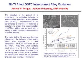
Thermal Expansion Influence of Ni content on thermal expansion Dependence of CTE on Ni content at 850oC
Supporting High Conductivity on the Cathode Side hydrogen replacement by air air H2 YSZ tube Interconnect disc Slight IC porosity provides penetration of hydrogen and keeps the composite in reduced state
Changes of TiO2 (Nb2O5) Resistance After Replacement of the Gas Environment a) b) Change of gas environment from air to hydrogen and back: a) –short time; b) –long time The slow change of the resistance is explained by an extremely low rate of oxygen diffusion into doped titania.
Conclusion • The novel composite interconnect consisting of nickel and titania doped by niobium oxide has high mechanical strength, and high electrical conductivity in air and fuel. • It withstands thermal cycling and oxidation by air. • The coefficient of thermal expansion may be adjusted by variation of the metallic and oxide component ratio. • Acknowledgements: This work was co-funded by NYSERDA (Project No 23644).