Download
1 / 9
90 likes | 92 Views
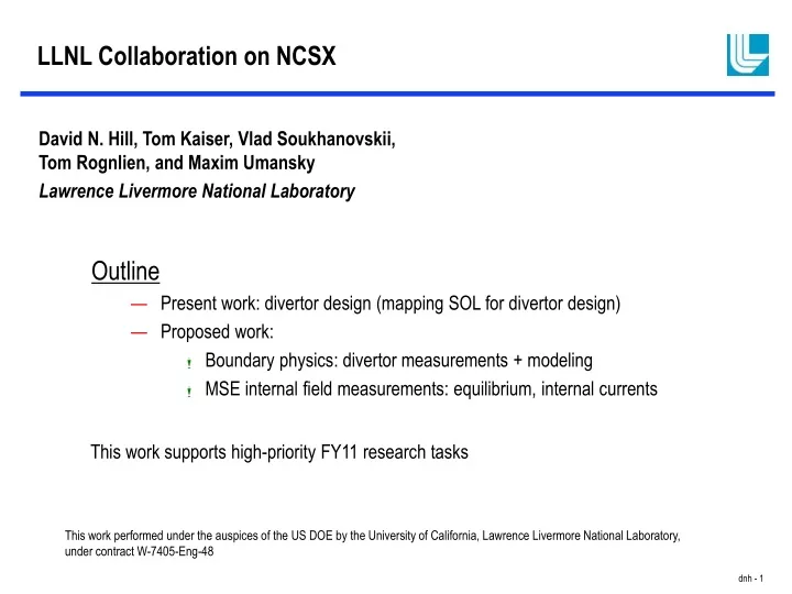
LLNL Collaboration on NCSX. Outline Present work: divertor design (mapping SOL for divertor design) Proposed work: Boundary physics: divertor measurements + modeling MSE internal field measurements: equilibrium, internal currents.

E N D
LLNL Collaboration on NCSX • Outline • Present work: divertor design (mapping SOL for divertor design) • Proposed work: • Boundary physics: divertor measurements + modeling • MSE internal field measurements: equilibrium, internal currents David N. Hill, Tom Kaiser, Vlad Soukhanovskii, Tom Rognlien, and Maxim Umansky Lawrence Livermore National Laboratory This work supports high-priority FY11 research tasks This work performed under the auspices of the US DOE by the University of California, Lawrence Livermore National Laboratory, under contract W-7405-Eng-48
LLNL began looking at boundary physics for NCSX in 2000 • Internal funding for three years • Engaged Greifswald W7-X boundary group to assist with development of 3D SOL model • Worked with W7-AS group to apply VMEC/MFBE/GOURDON codes to map structure of the proposed NCSX coil set • Began looking at potential diagnostics for SOL measurements. • Very modest OFES funding since 2002 • Focus on mapping structure of SOL plasma as equilibrium has evolved • Focus on mapping SOL to divertor structures to support design activies • Reduced the scope of our collaboration with Greifswald to periodic consulting on their 3D SOL code
Field line tracing using MHD equilibrium from either PIES or VMEC/MFBE determines SOL and divertor geometry • Extensive benchmarking activity during FY05-06 to compare SOL geometry as determined by PIES and VMEC/MFBE equilibrium codes. Some differences are observed, but within uncertainties. • Computed SOL geometry used in deriving conceptual design for divertor plates. SOL transport simulated by magnetic field line diffusion.
LLNL is supporting design of PFCs • Heat flux is estimated by mapping LCFS field lines to divertor targets. • Field lines are a bit short (higher Te at target), but density is higher (lower Te at target). Different than Local Island Divertors. • Do we need the inner target plates during early low-power operation?
Infrared and visible TV cameras can provide information on 3D SOL structure provided appropriate viewing geometry. • Wide-angle tangential views provide outline at single cross section. • Inversions possible with model of LCFS (similar to what we do now on DIII-D with recycling and ELMs). • Also possible to generate simulated diagnostic images. • Imaging through most ports will require re-entrant optics to obtain desired field of view, so most of the cost is related to engineering design activities.
Livermore Is Responsible for Divertor IR Imaging on DIII-D and Has Used the Data to Validate 2D SOL models • IR brightness converted to surface temperature, from which heat flux can be derived. • Heat flux profiles mapped to MHD equilibrium. • Measurements can be compared with simulations. Example shows UEDGE 2D simulation. • On DIII-D, divertor Thomson (LLNL-GA collaboration) provides 2D temperature and density to compare with simulation. 2d reconstruction of plasma pressure profile in detached divertor plasma in DIII-D.
LLNL Brings Experience Designing, Building, and Using World-Class DIII-D MSE System to NCSX Internal Current Profile Measurements. • MSE routinely used to constrain MHD reconstruction of DIII-D plasmas with strong current profile modification (Advanced Tokamak, Hybrid, Negative Central Shear, Current Holes, edge bootstrap currents). DIII-D will not run AT experiments without MSE. • Calibration for precision polarization measurements, proper line-of-sight, adequate spatial resolution, are key elements to successful MHD reconstruction. • Existing collaborations with U. Wisconsin and General Atomics complement strengths of the Livermore team.
BES measurements verify strong RSAE localization around qmin location BES measurements verify strong RSAE localization around qmin location 119346 A B MSE q-profile A Major Radius (m) 119345 B • BES makes radially localized measurements of density fluctuations • Combined with MSE, BES data confirm high-n RSAE density fluctuations are localized near qmin. Mike Van Zeeland – General Atomics
Some general comments on collaborations • Collaborations can bring many benefits to host institution • Unique skills/experience in personnel, new hardware capability • Potentially cheaper and/or more flexible workforce • Free energy and fresh ideas from an external without the “project” perspective • Collaborations can bring many benefits to the collaborating institution • New funding for people and equipment (as opposed to more work for same people) • Opportunity to expand scope of research, applying expertise to new problems • Increased recognition and invitation to branch out further, tackle bigger challenges. • Some key elements of successful long-term collaborations in experimental science • Fund people + instrumentation + design support (free energy, safety valve, tangible assets) • Have clearly defined institutional roles for collaborating institutions (more than individuals) • Provide professional growth opportunities for collaborators and help advertise role of host institutions