Download

1 / 28
280 likes | 549 Views
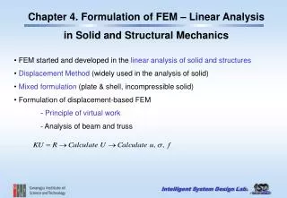
Bars and Beams FEM Linear Static Analysis. Stiffness matrix formulation: bar element. Uniform prismatic elastic bar of length L, elastic modululus E and area A ( 2 dof ) Only axial direct displacement are allowed.

E N D
Stiffness matrix formulation: bar element • Uniform prismatic elastic bar of length L, elastic modululus E and area A (2 dof) • Only axial direct displacement are allowed Forces that must be applied to the nodes in order to maintain the displacement state Nodal forces
Direct Method Nodal displacement vector • A column of K is a vector of nodal loads that must to be applied to the element to sustain a deformation state in which: • the corresponding nodal d.o.f has unit value; • all other nodal d.o.f. are zero. • For example with u1=1 and u2=0
Formal procedure • The direct methods can produce a stiffness matrix only for simple elements, where the relations between nodal displacements and loads are known. • For most general elements a general formula for k must be used • It can be derived by stating that work is done by nodal loads that are applied to create nodal displacements and this work is stored in the element as elastic strain energy • Stiffness matrix Bstrain displacement matrix E elastic modulus dVincrement of the element volume
Shape function matrix • To obtain B we write the axial displacement u of an arbitrary point on the bar as linear interpolation between its nodal value u1 and u2 Nshape function matrix • Each shape function Nidescribe how u varies with x when the corresponding d.o.f. ui is unity while the other is zero.
Stiffness matrix • Axial strain is the gradient of the displacement • For the bar problem, matrix E is simply the elastic modulus E, a scalar • dV is Adx • The equation for k becomes The definition of k guarantees that it will be a Symmetric matrix
Limitation of the two nodes bar element • It can represent only a constant state of strain • In terms of generalized coordinates • If axial force are applied only at nodes, the element agree exactly with a mathematical model that represents the bar as straight line having constant A and E between locations where axial forces are applied • If axial force are distributed along all part of the length or if the bar is tapered, then the element is only approximate • Distributed load can still be applied, in the form of equivalent forces applied to nodes
Simple plane beam element • Resist in plane bending and transverse shear forces (4 dof) Aarea of the cross section E elastic modulus Icentroidal moment of inertia Nodal displacements consist of lateral translations v1 and v2 and rotations qz1 and qz2 about the z axis The beam centerline has lateral displacement is v=v(x) v=v(x) is cubic in x for a uniform prismatic beam loaded only at its ends We will ignore transverse shear deformation, although commercial software account for it
Shape functions One d.o.f. has unit value and all other d.o.f. are zero
Stiffness matrix kij are nodal forces and moments that must be applied to sustain the assigned deformation state, positive direction are upward for forces and counterclokwise for moment To solve for the first column of k, the column vector the following conditions are used
Stiffness matrix • Each deformation state yields terms in one column of k • The result of this process is the element stiffness matrix which operates on the vector of nodal d.o.f.
Formal procedure for simple beam element • The general expression of stiffness matrix for flexural deflection is: where B is a matrix that yields curvature d2n/dx2 of the beam element from the product B d. In each case the expression: represents the strain energy in an element under nodal displacement d. In bars, strain energy depends on axial strain; in beams, strain energy depends on curvature.
In terms of generalized coordinates the lateral displacement is a cubic function in x: The bj terms can be stated in terms of nodal d.o.f. making the substitution at beam extremities, like, for example: Thus an alternative form for the lateral displacement uses shape function Ni where each Ni states the deflected shape associated with a particular end translation of rotation
Curvature in simple beam element The curvature of the beam element is expressed in matrix form using the derivative of the shape function and the nodal displacements Where strain-displacement matrix B is:
Stress in simple beam element Bending moment and flexural stresses are computed from curvature, which in turn depends on nodal d.o.f. d. If y is the distance from the neutral axis, the following holds: Flexural moment M caused by nodal displacement d varies linearly with x in each element
Limitation of the simple plane beam element • Under the usual restriction, that the beam is initially straight, linearly elastic, without taper,a beam subjected to forces and moment only at nodes, has a deflected shape that is cubic in x, just as described by the shape functions Ni • A FE model built of beam elements provides an exact solution when force and/or moment are applied to its nodes only. • A uniformly distributed load produces a beam deflection that is fourth degree in x. • Accordingly, beam elements are inexact under distributed loads, but exact results are approached as more and more elements are used in the FE model.
2D Beam Element • It is a combination of a bar element and a simple beam element, and it might also be called a plane frame element. • It resists axial stretching, transverse shear force, and bending in one plane. • Combining bar and simple beam stiffness matrices, the stiffness matrix of the 2D beam element is the following, indicating on the right the d.o.f. on which k operates:
3D beam element Web of beam section Local reference frame global reference frame A beam element in a general purpose FE program has three-dimensional capability and may also be called a “space beam” element. A global reference frame XYZ is introduced, while the longitudinal axis of the beam lies along a local x axis, defined by the coordinates of nodes 1 and 2, of a local reference frame xyz. In order to orient the local frame xyz, a node 3 is introduced, whose coordinates serve to orient the xy plane in XYZ space. In the example the xy plane is placed along the web of the beam section. No d.o.f. are associated to node 3.
d.o.f. of 3D beam element 6 dof for each node 12 dof for each element At each node the element has six d.o.f. (three displacements and three rotations) The matrix k is formulated in the local reference frame, then kis transformed so that global d.o.f. replace local d.o.f. at each node. The element resists forces in any direction and moments about any axis.
The following data are needed to define the 3D beam element: • Nodal coordinates (nodes 1, 2 and 3), for beam and its section orientation • Parameters: • A cross section area • E, G Young modulus and shear modulus (or Poisson’s coefficient n) • Iyy Izz section inertia moment about local y and z axis • J torsion constant • fy, fz shear deformation factors
3D beam element: some remarks L Additional data are needed for stress computation, such as the appropriate distance y in the flexure formula. If the section is noncircular, note that J is not the polar moment of inertia of the cross sectional area A. J is a property of the cross section, such that the correct relative rotation of nodes a and 2 under the torque T is given by TL/GJ. Often (especially for open sections, like the one of the example), is much lower than the polar moment of A
Properties of k (element) and K (structure) • Stiffness matrices k e K are symmetric. This is true for any element or structure when there is a linear relationship between applied loads and resulting deformations • Each diagonal coefficient is positive. This corresponds the say that, in a configuration where the corresponding d.o.f is the only one existing, a load ri and its displacement di must be directed in the same direction • A negative diagonal coefficient kii would mean that a load and its displacement are oppositely directed, which is unreasonable
Avoiding singularities for K • A structure that is unsupported or inadequately supported has a singular stiffness matrix K, and the software will not be able to solve the equation: K D = R • To prevent singularity, supports must be sufficient to prevent all possible rigid-body motions. • These are motions that produce no deformation of the structure. • For example, in a one element structure made of a simple beam element (4 d.o.f.): - if unsupported, it can have two rigid-body motions in the xy plane lateral translation and rotation about a point - is adequately supported if at least two d.o.f. are prescribed, expect that the two rotations are prescribed, in such case a rigid translation is possible.
Adequate support make the structure statically determined • More than adequate support make the support reaction statically indeterminate, but this is perfectly acceptable and it does not complicate the FE process in any way. • A structure may have a singular k matrix because it contains a mechanism. • Imagine a straight beam, attached to a rigid support at each end, and modeled by two beam element. The model is stable and has not mechanism. • If the two beam element are replaced by two bar elements The structure is a mechanism because two collinear bar elements can not resist a lateral force applied to the central node.
Mechanical loads • Load may be applied as: • - a concentrated force or a moment directly to a node • - as force or moment distributed along a line • - as a surface pressure. • Body force loading, which acts at every material point in the body include self weight (gravity) and acceleration (inertia forces) • Thermal loading comes from temperature changes. • Moment load can be applied to a node if at least one element connected to that node has rotational d.o.f. in its stiffness formulation. • Input data to software consists of the magnitude, direction, and node associated with the force or moment.
Line loads • Axial force, weight or resistance to acceleration , (line load q [N/m]) uniformly distributed on a bar element, must be converted into equivalent nodal loads • Total load on an element is qL, Half of this load is applied to each node • If two collinear elements of length La and Lb are connected, the node they share will be loaded by a total force qLa/2+qLb/2. • Most software are able to accomplish the conversion, the user need only tell the software what the loading is and where it acts.
Transversal loads • Theory indicates that a transversal load (q [N/m]) uniformly distributed on a beam element converted into equivalent nodal loads that consists of forces and moments. • These loads are the support reactions (direct opposite) for a uniform beam fixed at both ends and uniformly loaded. • If elements of equal length and equal distributed loads are assembled, moment loads cancel at nodes shared by two elements.
Stresses • A FE software calculates the displacements first, and form these the stresses are obtained. • Nodal displacements are more accurate than stresses, because stresses are proportional to strains, and strains are derivatives of the displacements. • Stresses are well approximated at the centre of the element, as well as the mean stress on the element • Stresses at boundaries are usually not well approximated. Maximum value not well approximated